

TAGGED: coordinate-system, fluent
-
-
February 7, 2022 at 11:57 am
amind
SubscriberHello everyone
I am simulating a 2D vertical axis wind turbine in ANSYS Fluent software. A schematic of this turbine can be seen in Figure1.
Figure1:
February 7, 2022 at 4:50 pmRob
Forum ModeratorYou need a round separate fluid zone for each foil. You then set the reference system for each fluid. Read up on sliding mesh, and make sure you understand absolute and relative in the cell zone panels.
February 8, 2022 at 11:59 amSubscriberThanks Rob
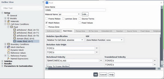
I followed your advice. I used sliding mesh for the turbine rotor (large circle).
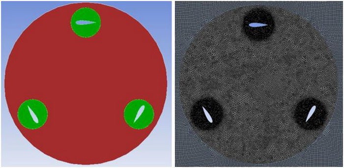
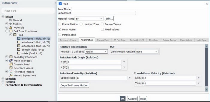
I also created a circular zone around each airfoil and set them as "relative" to the large circle in the "cell zone panel".
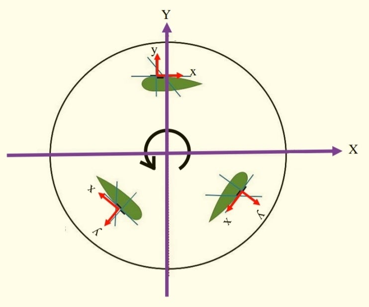
But I still do not know how I can set a "separate coordinate system" for each "zone".
In other words, I do not know in which panel of Fluent software I can adjust the settings for the new coordinate systems?
February 8, 2022 at 12:09 pmForum ModeratorCell zone as you've shown above. Each rotating zone needs it's own axis and speed. For the airfoil zones use the value at the start of the calculation, ie on the mesh you read in. Make sure you save the case somewhere safe (export if you're using Workbench) as errors will result in the airfoils orbiting the main rotation zone: it's very pretty but not overly useful as a simulation and fixing it at that stage is near to impossible.
February 8, 2022 at 12:53 pmSubscriberThanks Rob, but I do not want airfoils to rotate; I just want to have a local coordinate system (x, y) on each airfoil.
Because I want to apply a "source term" to each airfoil using "Named Expression" in the x and y directions. (A body force in the x and y directions is applied to each airfoil to control the flow separation by increasing the momentum of the boundary layer)
Fluent software applies these source terms in the (X, Y) direction of the global coordinate system, but I want these forces to be applied in the (x, y) direction of local coordinate systems on each airfoil.
February 8, 2022 at 1:47 pmAmine Ben Hadj Ali
Ansys EmployeeYou cannot use that till now. There is a workaround to create different reference frames and cerate profiles associated with these new reference frames or even do coordinate transformation with this new reference frames (this will require some UDF for now). So for now unfortunately usage of reference frame is limited.
Viewing 5 reply threads- The topic ‘Create new coordinate system in Ansys Fluent’ is closed to new replies.
Innovation Space Trending discussions
 Top Contributors
-
peteroznewman
 4763
4763 -
scabo
 1565
1565 -
Dennis Chen
 1386
1386 -
javat33489
 1242
1242 -
Shyam Prasad V Atri
1021
Top Rated Tags
© 2026 Copyright ANSYS, Inc. All rights reserved.
Ansys does not support the usage of unauthorized Ansys software. Please visit www.ansys.com to obtain an official distribution.
-


The Ansys Learning Forum is a public forum. You are prohibited from providing (i) information that is confidential to You, your employer, or any third party, (ii) Personal Data or individually identifiable health information, (iii) any information that is U.S. Government Classified, Controlled Unclassified Information, International Traffic in Arms Regulators (ITAR) or Export Administration Regulators (EAR) controlled or otherwise have been determined by the United States Government or by a foreign government to require protection against unauthorized disclosure for reasons of national security, or (iv) topics or information restricted by the People's Republic of China data protection and privacy laws.


