
-
-
December 9, 2021 at 1:42 pm
Van Toan Nguyen
SubscriberHello everyone,
I am modeling deformation of a thin tube caused by high pressure inside. Material properties of the tube are not uniform along the tube axis. It is seem to be impossible to simulate with solid body (I have tried several times). Therefore, I used shell body with uniform shell thickness at initial state. I succeed for getting deformed shape.My question is: Is there any option to get variation of the tube thickness (Poisson's Ratios were defined in Engineering data)?. I tried to import displacement obtained from simulation of shell body into simulation of solid body, but it seem to be tedious way.
December 10, 2021 at 1:59 pmJohn Doyle
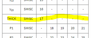
Ansys EmployeeIf this is a surface body meshed with SHELL181 elements, it is possible to postprocess the new thickness.Refer to Table 181.2 of the Elements Manual for SHELL181. You will find ÔÇÿTHICKÔÇÖ listed as a summable miscellaneous results item (SMISC=17) in this table.
In Workbench, you would need a command object under Solution branch that looks something like the following:
/SHOW,png
set,last,last
esel,s,ename,,181
plesol,smisc,17
/SHOW,term
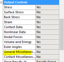
Be sure to set General Miscellaneous results to ÔÇÿYesÔÇÖ under Analysis Settings=>Output ControlsÔǪ before running the analysis
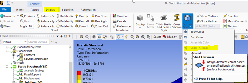
December 10, 2021 at 5:52 pmAnsys EmployeeActually, it looks like we expose this feature in Mechanical GUI, if you have shell bodies in your model.
December 11, 2021 at 12:52 amSubscriberThank you for your reply.
I added a command "et,matid,SHELL181" to convert element type. I also meshed surface body with linear element type. I then followed your guideline.
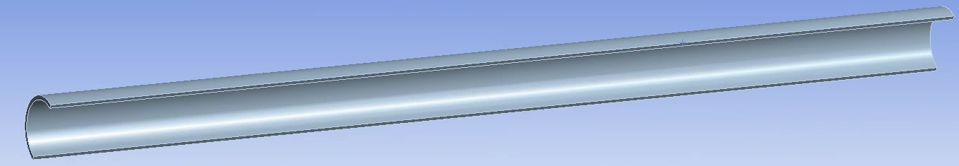
However the result of direction deformation shows that the shell thick is still uniform
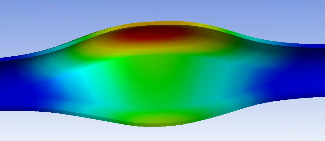 (This is only partial result because the simulation was not fully converged)
December 13, 2021 at 2:03 pmAnsys EmployeeIs this a surface body or a solid body.
Sorry for the confusion, but this needs to be a surface body to be meshed successfully with shell181 elements. It cannot be a solid body.
Also, I am not sure you will "see" the change in thickness, just a contour plot in the shell181 elements illustrating the distribution of the change.
December 13, 2021 at 2:11 pmSubscriberYes , it is surface body. There is only one cylinder surface.
December 13, 2021 at 2:11 pmSubscriber
Viewing 6 reply threads- The topic ‘Change of thickness of shell body (Ansys Workbench)’ is closed to new replies.
Innovation Space Trending discussions
 Top Contributors
-
peteroznewman
 5264
5264 -
scabo
 1859
1859 -
Dennis Chen
 1398
1398 -
javat33489
 1256
1256 -
Shyam Prasad V Atri
1021
Top Rated Tags
© 2026 Copyright ANSYS, Inc. All rights reserved.
Ansys does not support the usage of unauthorized Ansys software. Please visit www.ansys.com to obtain an official distribution.
-


The Ansys Learning Forum is a public forum. You are prohibited from providing (i) information that is confidential to You, your employer, or any third party, (ii) Personal Data or individually identifiable health information, (iii) any information that is U.S. Government Classified, Controlled Unclassified Information, International Traffic in Arms Regulators (ITAR) or Export Administration Regulators (EAR) controlled or otherwise have been determined by the United States Government or by a foreign government to require protection against unauthorized disclosure for reasons of national security, or (iv) topics or information restricted by the People's Republic of China data protection and privacy laws.
