
TAGGED: workbench-contacts
-
-
November 1, 2021 at 2:27 pm
chenqingsen
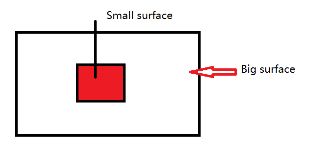
SubscriberI have an ansys classic model, and export to cdb file which including nodes components. The I use external model to import the cdb file, and I have select to crest Gemotry Facce Components, but some nodes compnents can't creart the surfeace, for example a small part of a big surface. So how to use the nodes name selection to creat contact ?The defaut contact use the geometry face, is there a way to choose a node name selecction to creat contact ?
November 10, 2021 at 9:29 pmSheldon Imaoka
Ansys Employee
In Mechanical APDL, there is a 'mesh-only' element type called MESH200. These elements are mesh-only and do not change the physics or structure. For the 'faces' you want to define as contact, what you will need to do in Mechanical APDL before exporting the CDB file is the following:
Define MESH200 element type and appropriate keyoption for the shape. Please refer to Elements Reference for details.
Select the nodes on the 'surface', activate your MESH200 element type, then use ESURF to generate the elements. (Repeat this for all locations, preferably using different MESH200 element type for distinct regions.)
Export the CDB file from Mechanical APDL using CDWRITE
In Workbench External Model, there is an option "Process MESH200 Elements". This is turned off by default, so you have to turn it on. If you are using an existing project, right-click on External Model system to 're-read data files', so the new CDB file will be read in.
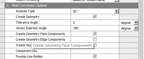
In the linked Mechanical system, ensure that you have "Create Geometry Face Components", as you have shown in your screenshot.
When you open Mechanical, the MESH200 surface bodies will appear - you can suppress them. However, Named Selections of the underlying mesh should appear in Named Selections as well. These can be used in Contact Regions.
Basically, what happens is that we have nodal components or element components in Mechanical APDL, but we don't have 'face' components. Using MESH200 to define the surfaces is thus needed to define a 'face'. Otherwise, we only have a collection of nodes (nodal component).
Regards Sheldon
November 12, 2021 at 3:29 pmSubscriberOK. If the component is small surface node of big surface. When I import the cdb file´╝îit can creat the big surface. So I want to know using the MESH2000 element can creat the face which can be used as target surface ?
November 12, 2021 at 3:40 pmAnsys Employee
Yes, you can do what you noted in your reply. Define MESH200 with the appropriate keyoption - for example, if the parts are meshed with 10-node tetrahedral elements, you can use "ET,10,200,5" to define element type ID #10 as a 6-node triangle. Select the nodes either on the small surface or big surface (pick one), then, use TYPE,10 and ESURF to create the MESH200 elements. If you follow the steps outlined in my earlier reply, the surfaces should be separate when you import into Mechanical.
Regards Sheldon
November 14, 2021 at 6:50 amSubscriberOK´╝îthinks. I will try.
Viewing 4 reply threads- The topic ‘How to use node name selection to creat contact in workbench ?’ is closed to new replies.
Innovation Space Trending discussions
 Top Contributors
-
peteroznewman
 6535
6535 -
scabo
 1906
1906 -
Dennis Chen
 1463
1463 -
javat33489
 1311
1311 -
Shyam Prasad V Atri
1022
Top Rated Tags
© 2026 Copyright ANSYS, Inc. All rights reserved.
Ansys does not support the usage of unauthorized Ansys software. Please visit www.ansys.com to obtain an official distribution.
-


The Ansys Learning Forum is a public forum. You are prohibited from providing (i) information that is confidential to You, your employer, or any third party, (ii) Personal Data or individually identifiable health information, (iii) any information that is U.S. Government Classified, Controlled Unclassified Information, International Traffic in Arms Regulators (ITAR) or Export Administration Regulators (EAR) controlled or otherwise have been determined by the United States Government or by a foreign government to require protection against unauthorized disclosure for reasons of national security, or (iv) topics or information restricted by the People's Republic of China data protection and privacy laws.
