TAGGED: interconnect, lumerical, s-parameters
-
-
November 1, 2021 at 11:41 am
iiskanda
SubscriberDear community,
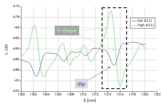
I'm trying to simulate cascaded interfaces through "Optical N port S-parameter elements". Both complex S11 and S21 are not constant. When S11 has low values the spectrum I get through an ONA has some dips, what I observe is that when S11 gets high values those dips get a weird S-shape, see attached. Why is this happening?
Regards,
Ilias
November 1, 2021 at 2:38 pmiiskanda
SubscriberFollowing up on my previous post, I'd like to mention that I connect the S-parameter elements with straight waveguides and attenuators as in the image attached. Is there any case that I connect wavelength-dependent elements (S-parameter) with non-wavelength-dependent (straight waveguide + attenuators) that causes the problem?
Regards Ilias

May 18, 2022 at 1:37 pmOdebowale
SubscriberHello iiskanda Sorry I am currently a similar problem, I don't know if you have got solution to the posted question.
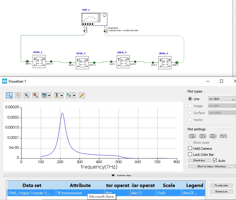
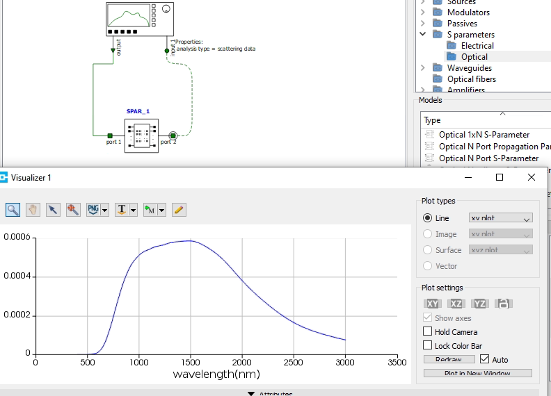
For my case, I am working on layered design ( consisting of 4 layers), so I extracted S matrix for each of the layer in FDTD then imported it interconnect. So, I have four different files each loaded to a separate "Optical N port S-Parameter" in interconnect. When I connected them connected using wire, the output transmission is not the same as the one I got when I extracted the S-matrix for the whole structure (without going through the layers one by one ). Is here something I am not getting right? Attached are copies of the two procedures: layer by layer extraction and extracting it for the whole design once.
In addition to the above question, is there away I can I visualize reflection/ plot from interconnect just like I did for transmission?
Thanks


May 19, 2022 at 3:59 amMay 19, 2022 at 11:11 amiiskanda
SubscriberHi Gwang This is the 20log10(abs(S21)) value for both curves. That's why I mention IL on the y-axis.
Viewing 4 reply threads- The topic ‘Cascaded S-parameters Interconnect’ is closed to new replies.
Innovation SpaceTrending discussionsTop Contributors-
4974
-
1650
-
1386
-
1242
-
1021
Top Rated Tags© 2026 Copyright ANSYS, Inc. All rights reserved.
Ansys does not support the usage of unauthorized Ansys software. Please visit www.ansys.com to obtain an official distribution.
-
The Ansys Learning Forum is a public forum. You are prohibited from providing (i) information that is confidential to You, your employer, or any third party, (ii) Personal Data or individually identifiable health information, (iii) any information that is U.S. Government Classified, Controlled Unclassified Information, International Traffic in Arms Regulators (ITAR) or Export Administration Regulators (EAR) controlled or otherwise have been determined by the United States Government or by a foreign government to require protection against unauthorized disclosure for reasons of national security, or (iv) topics or information restricted by the People's Republic of China data protection and privacy laws.


