TAGGED: 2d-materials-and-metals, Diverging-fields
-
-
September 23, 2021 at 10:27 pm
aaditya
SubscriberHello,
We are trying to calculate the Reflectance spectrum for a layered structure. The materials we are using are mos2, mose2, silver on a glass substrate.
The structure consists of a monolayer of mos2 or mose2 placed on a glass substrate. A silver layer of 50nm is laid on top of mos2/mose2. The silver has an etch at its center. Then we shine light in the 400 nm to 800nm wavelength range to get the reflection spectrum.
We have tested the simulation with just the 2D materials, or just silver, and good results (reproduced experimental reflectance spectrum), but when we use them all together most of the time the simulation diverges. I have played with the step size, dt, mesh accuracy and mesh refinement parameters but the simulation still diverges. So far only one simulation with mose2 has finished but the results don't make sense as the Reflection spectrum goes up to 10000.
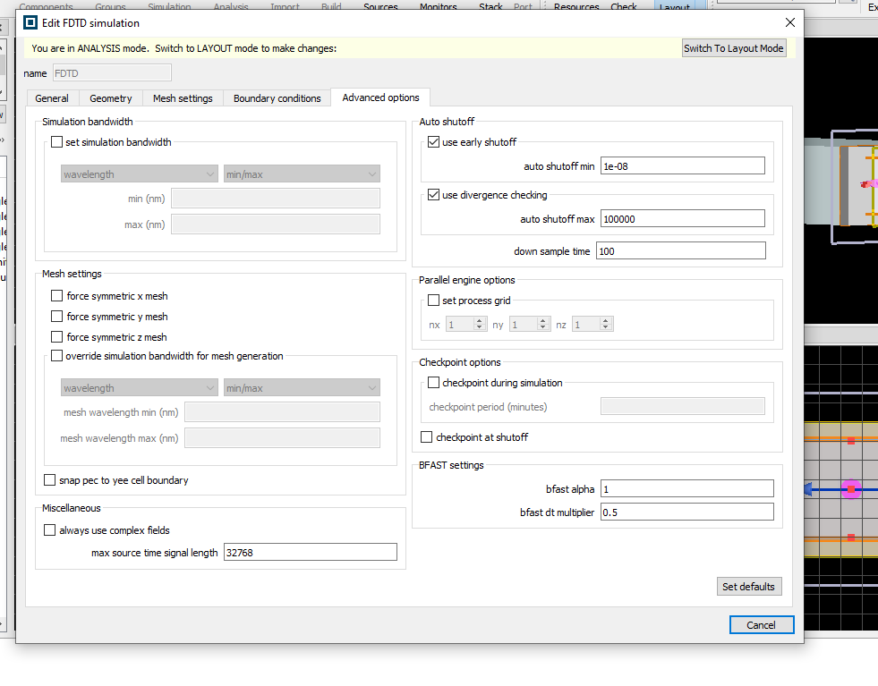
I am attaching pictures of the simulation setup here. If someone can take a look and tell us what we are doing wrong it will be a great help.
With regards
Anikeya
September 24, 2021 at 5:16 pmGuilin Sun
Ansys EmployeeFor such devices involving heavy lossy metal and 2D materials, it might be a challenge but can have non-diverging result. Some suggestions are
1: use regular mesh accuracy 2, or 3, instead of 7, since you have already used override mesh to make the local etch finer.
2: I guess the structure is 2D material sandwiched the metal on a substrate ? if so, and you want to have finer mesh for the structure, please only cover the Silver, as the override mesh will have 2 mesh buffer with the same finer mesh. so no need to cover large region. Doing so will release the mesh sizes in air and SiO2 gradually to the background mesh accuracy.
3: make sure the PMLs are located in uniform background mesh region.
4: check the farfields using visualizer to see if there are some large diffraction angles, or you can also use grating analysis to check the diffraction angles. If the angles are large, please more PML layers. and If the diffraction angles are larger than 60~70 deg you may consider to use Steep Angle PML with more number of layers.
5: PML thickness is usually suggested to have half wavelength, which can be roughly measured by the Ruler in the tool bar on the left.
6: if it is still diverging after the above modifications, you may consider redoing the silver material fitting. Sometimes an artificial peak in the material fitting can cause issues.
7: you may also use time monitor to identify the resonance and if the resonant wavelengths are outside of the desired range, you can use longer pulse by setting the source in time domain.
October 26, 2021 at 4:38 amaaditya
SubscriberSorry for the later response. Your directions helped a lot. Thank you
Viewing 2 reply threads- The topic ‘Need help with this FDTD simulation of 2D materials and metals’ is closed to new replies.
Innovation SpaceTrending discussionsTop Contributors-
4798
-
1576
-
1386
-
1242
-
1021
Top Rated Tags© 2026 Copyright ANSYS, Inc. All rights reserved.
Ansys does not support the usage of unauthorized Ansys software. Please visit www.ansys.com to obtain an official distribution.
-


