TAGGED: ansys-circuit, circuit-design, hfss, impedance-matching, s-parameters
-
-
September 3, 2021 at 9:20 am
Dommeti
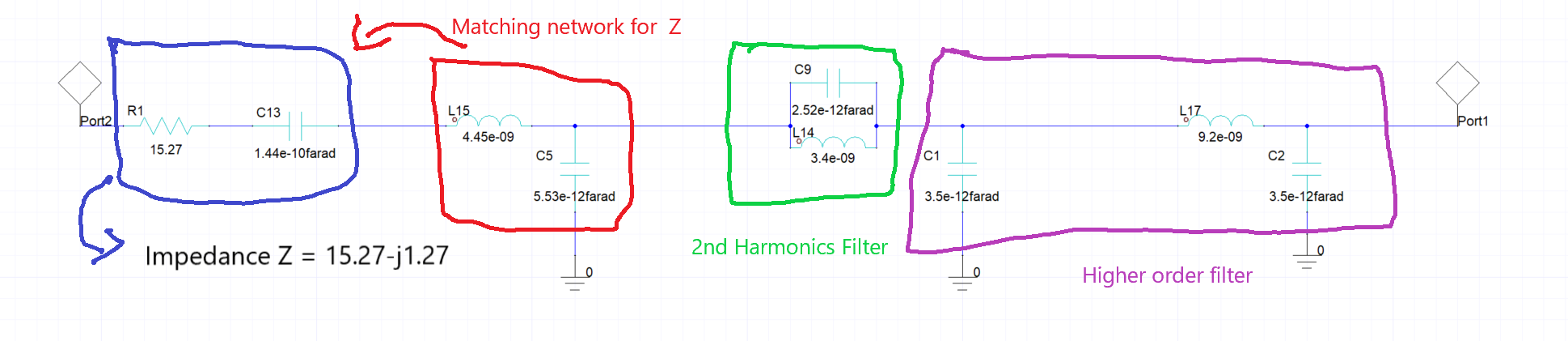
SubscriberI am new to Ansys. I am designing matching network at 868MHz frequency. I have a source impedance of Z=15.27-j1.27. In order to match that with 50 Ohm, I implemented LC matching network (red color). After that in order to filter second harmonics, I implemented band stop filter (green color). Following that, in order to filter higher order, I implemented CLC filter (purple color). All these are designed for 868MHz frequency.
But my problem now is that, when I implemented and analyzed this circuit in Ansys Circuit, I am not getting required output. I have attached my circuit and its result below. Please help me to solve this and correct if there are any mistakes in the component values at the required frequency 868MHz.
September 16, 2021 at 11:36 amPraneeth
Ansys Employee
We appreciate your patience.
Please note that you can incorporate source impedance into the port definition, so it is not required this explicitly into the circuit.
I would like to know how you have designed the matching circuit for the mentioned source impedance.
You can use the smith tool embedded with the Ansys circuit tool for designing the matching circuit. Please go through this course on Cosimulation which shows how to do matching using Smith tool - Cosimulation Using Ansys HFSS - ANSYS Innovation Courses.
I am also interested to see how you are defining the excitation and analysis for removing the second and higher order harmonics using the sub circuits.
All the very best.
Viewing 1 reply thread- The topic ‘Ansys Circuit and it’s response’ is closed to new replies.
Innovation Space Trending discussions
 Top Contributors
-
peteroznewman
 5834
5834 -
scabo
 1906
1906 -
Dennis Chen
 1420
1420 -
javat33489
 1305
1305 -
Shyam Prasad V Atri
1021
Top Rated Tags
© 2026 Copyright ANSYS, Inc. All rights reserved.
Ansys does not support the usage of unauthorized Ansys software. Please visit www.ansys.com to obtain an official distribution.
-