

-
-
September 3, 2021 at 1:55 am
hkanakri
SubscriberHello All,
Designing PM-Synchronous generator in RMxprt requires selecting the "AC" as control type in the Machine setup, also selecting the circuit type (The way the circuit is controlled). There is No circuit data properties exist since the AC is selected as the Control Type.
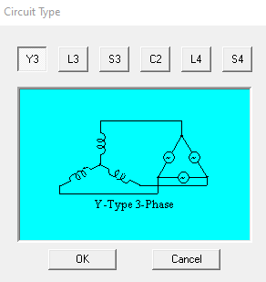
I need some clarification about the circuit type when selecting the AC control type. For example, selecting the Y3 circuit, then, What does the delta side represents? and what does the Y-connected inductors represent? Please see the pictures below.
September 6, 2021 at 2:19 pmNavya Chode
Forum ModeratorHi @Haitham_Kanakri The Y-connected inductors represent the machine winding and the delta side represents how the sources is connected.
You can analyze the RMXpert design and then create a maxwell design from it to see the Maxwell circuit and connection to understand better.
Regards Navya
September 6, 2021 at 6:04 pmSubscriberDear Navya,
Thank you for clarification. When I created maxwell 2D design from RMxprt it didn't create the Maxwell circuit. Unlike the maxwell 3D, it created the maxwell circuit for my machine. Can you please clarify why is this difference ? The confusion here that this machine is a permanent magnet Independent generator and does not require external field winding, so why RMxprt asking for Control type and circuit type in this case?
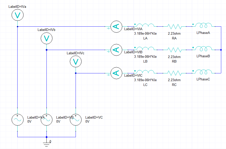
Also, where is the delta connected sources in the maxwell circuit below? Can you please explain what is the difference between LA and LPhaseA in this circuit ? and What is RA here? is it the per phase load resistance as shown in RMxprt design sheet ? Should it be the armature winding resistance?
Thank you Haitham
September 7, 2021 at 11:44 amForum ModeratorHi @Haitham_Kanakri RMXprt is a template-based design tool. you can change from motor to generator in the solution type. So some parameters remain as it is irrespective of it is motor or generator.
Let me cross-check on what I told you about circuit type (YE, L3..) and get back to you.
Coming to the circuit and maxwell model
LA, LB, LC represent the end winding leakage inductances calculated from RMXprt. you can find these parameters at the end of the RMXprt design sheet. Similarly, RA, RB, RC are terminal resistance of the stator winding.
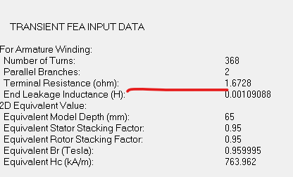
LPhaseA, LPhaseB, LPhaseC, are the winding inductances. which will be calculated in maxwell.
Since a PM motor can be run as a generator and vice-versa. The Maxwell generator model created from RMXprt might be similar to the motor. You can run the simulation as it is and see the induced voltage in the winding in the results plots.
If you have a load. You can also add a load at the end of the three phases in the circuit instead of the voltage sources. you can edit the circuit, export netlist, and the link again to the excitation in maxwell.
Regards Navya
Viewing 3 reply threads- The topic ‘Designing Adjust-Speed PM Synchronous Generator in RMxprt’ is closed to new replies.
Innovation Space Trending discussions
 Top Contributors
-
peteroznewman
 6520
6520 -
scabo
 1906
1906 -
Dennis Chen
 1463
1463 -
javat33489
 1310
1310 -
Shyam Prasad V Atri
1022
Top Rated Tags
© 2026 Copyright ANSYS, Inc. All rights reserved.
Ansys does not support the usage of unauthorized Ansys software. Please visit www.ansys.com to obtain an official distribution.
-


The Ansys Learning Forum is a public forum. You are prohibited from providing (i) information that is confidential to You, your employer, or any third party, (ii) Personal Data or individually identifiable health information, (iii) any information that is U.S. Government Classified, Controlled Unclassified Information, International Traffic in Arms Regulators (ITAR) or Export Administration Regulators (EAR) controlled or otherwise have been determined by the United States Government or by a foreign government to require protection against unauthorized disclosure for reasons of national security, or (iv) topics or information restricted by the People's Republic of China data protection and privacy laws.

 You are navigating away from the AIS Discovery experience