TAGGED: fluent-meshing, Mesh-Interface, sliding-mesh
-
-
September 2, 2021 at 10:00 am
alfnarso
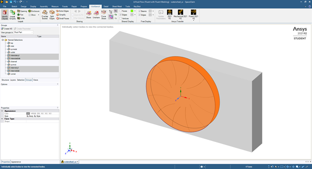
SubscriberI am trying to set up a simulation of waterwheel using Fluent with Fluent Meshing and handle the static and rotating regions using sliding mesh. However I observed the nodes at the static interface move along with the nodes of rotating interface, which results in distorted elements at the interface. Any suggestions to solve the problem?
For your information, the geometry was set up using SpaceClaim, and "Share Topology" was applied with the interfaces shown below:
September 2, 2021 at 4:03 pmRob
Forum ModeratorFluent Meshing doesn't let you set up the non-conformal. If you use Fluent Meshing you need to then slit the interior boundary between the wheel & background. The easier approach is to mesh the two bodies separately and then append the wheel mesh in Fluent: be very careful with units as it's common to read one mesh in mm and the second in metres.....
September 3, 2021 at 3:44 amSubscriberThank you Rob, for pointing out the root of the problem. I have created the mesh for the wheel and stationary background using Fluent Meshing and separated the mesh using the following steps:
Export and save the mesh containing both wheel and stationary background (domain_full.msh.h5).
Delete the mesh of stationary background (Menu -> Mesh -> Manage and delete Cell Zone in dialog box), delete volumetric region of stationary background (right click on the region in Outline View window the select Manage -> Delete), then export and save the mesh (domain_rotreg.msh.h5).
Import domain_full.msh.h5, delete mesh and volumetric region of the wheel using the technique in step 2.
Import domain_rotreg.msh.h5 with "Append File(s)" option enabled, export the mesh and overwrite domain_full.msh.h5.
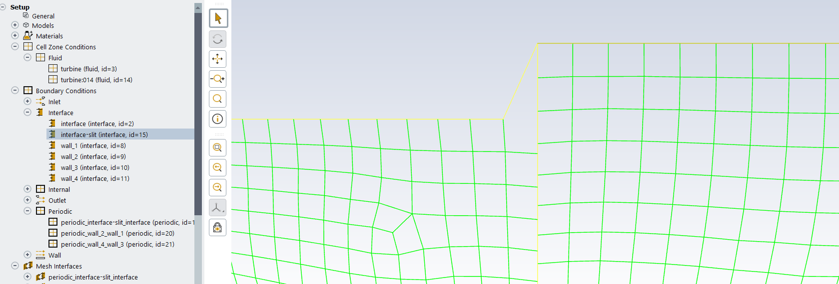
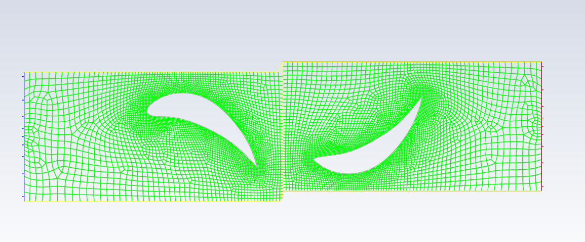
Now, we can close Fluent Meshing and run Fluent for solution set up. The mesh interface can be set up by change type of the interface zones from Internal to Wall, and then to Interface, and finally apply the "Manual Create" feature. In this way, when the nodes at rotating interface move, the nodes at the stationary interface do not move, and thus the problem with distorted elements has been solved!
September 3, 2021 at 9:54 amForum Moderatorpretty much, there's an easier way using slit boundary (/mesh/modify-zones in the TUI) but your way is "easier" for a less experienced user.
October 8, 2021 at 3:27 pmsidshr
SubscriberHello Rob, sorry to intrude. I am facing similar trouble and I used 'mesh modify-zones slit-face-zone' to decouple faces to form slits and then to create interfaces. As with the case, the node seems of the sliding interfaces are not decoupled and thereby, leading to skewed cells (fig.1 - after I timestep of 1e-5s) and negative volumes. I also tried appending two domains individually and it worked for the interface but caused another issue. This issue is that when I am converting tet mesh (created in icem) into polyhedral (in fluent), I am getting regions with holes (could be some tolerance issue?) on the interface. Any pointers on how to make sliding mesh work (decoupling) without going through the individual importation of two domains. Interestingly, the holes in polyhedral conversion are not observed when they are imported as a single file.
February 10, 2023 at 11:14 amJake Upsher
SubscriberHello Rob (Ansys Employer). Are you able to share the details on the easier method using slit boundary. I have slit my interface but the top and bottom nodes remain attached. Many thanks!
 Viewing 5 reply threads
- The topic ‘How to set up sliding mesh interface in Fluent with Fluent Meshing’ is closed to new replies.
Innovation Space Trending discussions
 Top Contributors
-
peteroznewman
 6570
6570 -
scabo
 1906
1906 -
Dennis Chen
 1463
1463 -
javat33489
 1311
1311 -
Shyam Prasad V Atri
1022
Top Rated Tags
© 2026 Copyright ANSYS, Inc. All rights reserved.
Ansys does not support the usage of unauthorized Ansys software. Please visit www.ansys.com to obtain an official distribution.
-