

-
-
July 31, 2021 at 2:28 pm
KSD
SubscriberI have created a 2-D surface design in solid works with many partitions, in order to create a structured mesh with better control for each faces and then transported it into Ansys as Parasolid (x_t) file.
(I know step file can be used as well but the problem with step file is, it will combine all partitions as one surface body, which will not allow me to hide any one particular faces and do meshing operation on that face alone in Ansys Meshing)
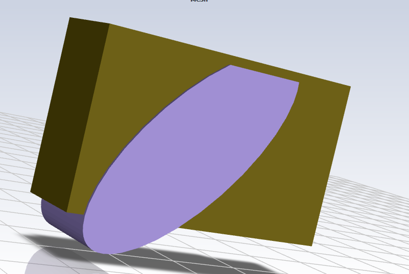
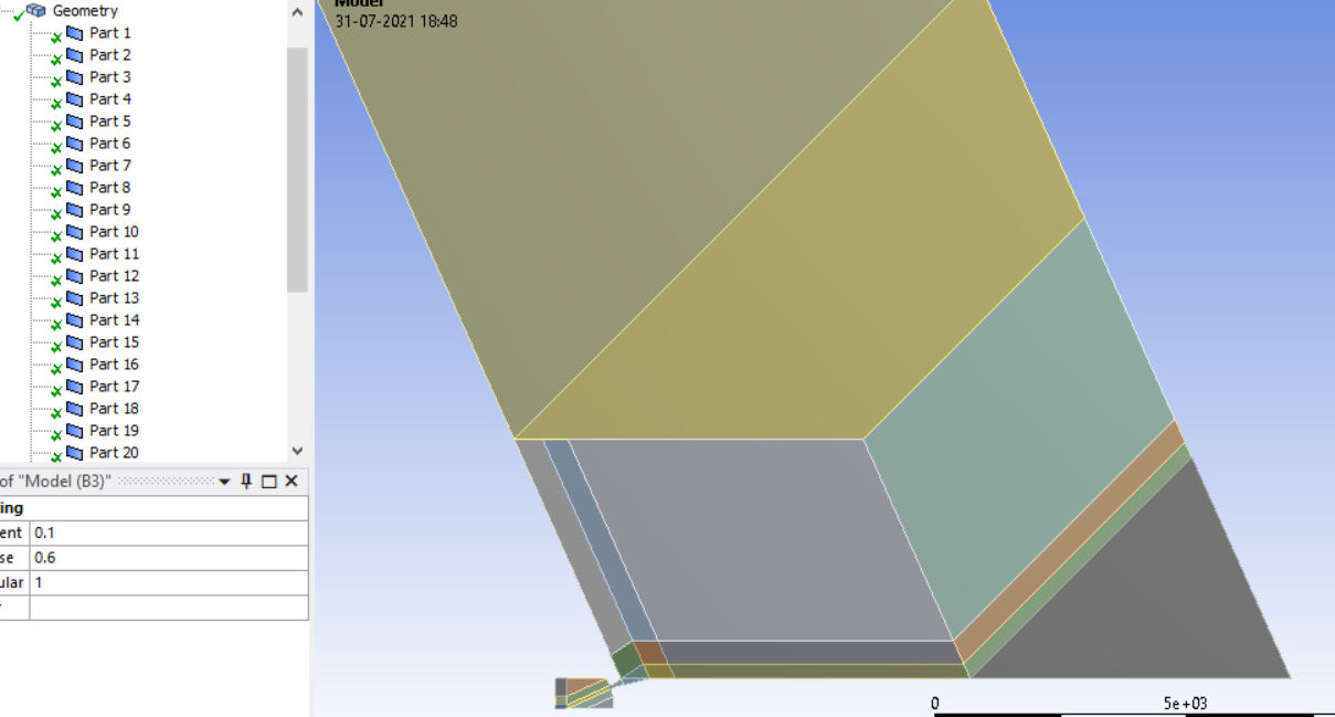
In the image below you can see the partitions of domain I did.
August 1, 2021 at 2:30 pmSubscriberCould you please help?
August 2, 2021 at 12:17 pmKarthik Remella
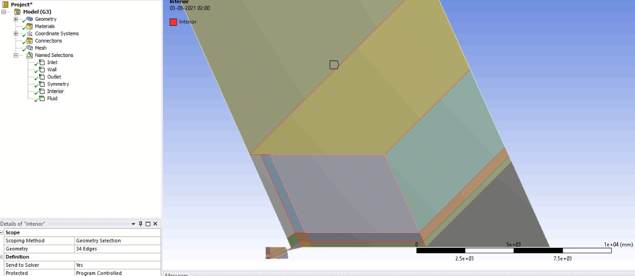
AdministratorHello If these are all internal partitions on your geometry (for a structured mesh), you can create a named selection called - 'Interior' in Meshing. This would create an interior face zone and the assigned BC in Fluent would automatically be 'Interior'.
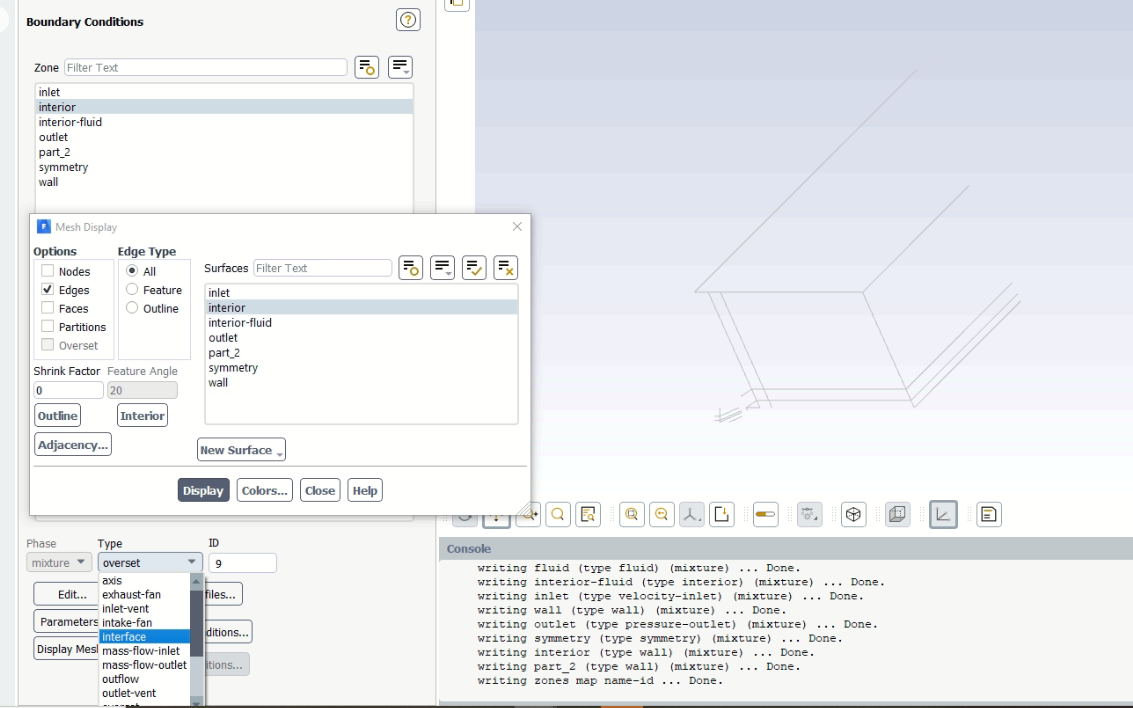
If you do not wish to go back to Meshing, you can change the BC type from Interface to Interior directly in Fluent. Just right-click and see the BC type on the boundary currently referred to as 'part_1'.
Karthik
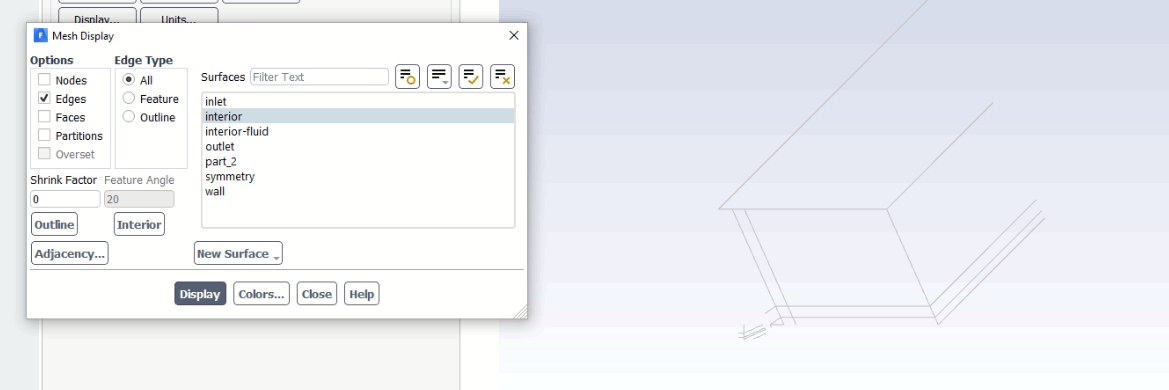
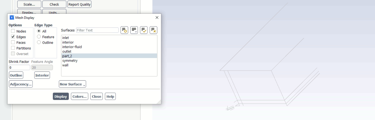
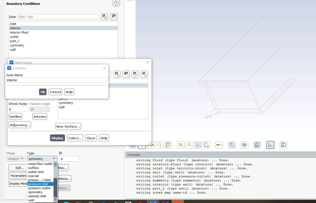
August 2, 2021 at 8:49 pmSubscriberSir, I did as you mentioned, but nothing changed. When I gave Interior for partition line in named selection and imported to fluent, it created that named selection which I gave but along with part_2 which also represents the same partition lines.
And Sir I don't know how to put the selected boundary as interior because I cannot see any option like that In Boundary Conditions, you can also check, I have scrolled down to the bottom bar but no option like interior is found. Or is there any other method to define that?
 Can you please help how to solve this?
Sorry for posting the same query in other section because I thought that only fluent related post will be solved in that section, that's why I later post the same query in the preprocessing section.
Is there any other options like delete the discussion which I created from my side?
August 2, 2021 at 8:55 pmAdministratorHello How many cell-zones is Fluent reading in your mesh? Are all the cell-zones Fluid (and same material)? Can you make sure of this in Fluent?
Karthik
August 3, 2021 at 12:07 amSubscriber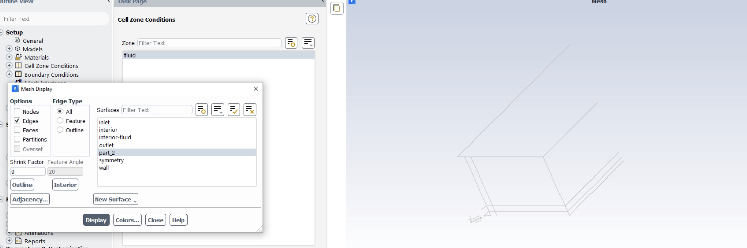 Sir, you can see in the above image that only one cell zone is present, which is assigned to fluid (air).
August 3, 2021 at 10:58 amRob
Forum ModeratorWhat is the problem with the lines? As an interior surface it's not doing anything so won't alter the result.
August 3, 2021 at 2:29 pmSubscriber@Rob Sir, the partition lines are assigned to wall by default which I think is not right, but if I consider them as interface then I am not able Initialize the solution due to unassigned interface.
Are you telling me to apply wall to this partition lines and it will still not alter the results?
August 4, 2021 at 1:01 pmForum ModeratorDid you do a share topology operation in the geometry tool?
August 4, 2021 at 5:12 pmSubscriber@Rob Sir, Yes share topology worked. But now it is same as step file. I cannot separately assign different sizing to different faces connected by same edge, seems like it is not logical to do like that.
You are great Sir, thanks for helping me.
August 5, 2021 at 12:35 pmForum ModeratorDo the meshing tutorials as they should clarify things. For a conformal mesh the edge common to two faces must have the same number of nodes on it. We can use nonconformal interfaces but given your decomposition it'd be an overly complicated mess for no benefit.
August 5, 2021 at 5:50 pmSubscriber@Rob Sir, I think in Ansys meshing for the cased of 2D, you have Multizone or Quad Method, Face/Edge Sizing ,Inflation and Face Meshing.
These are the tools which can be used for creating structured mesh and I have tried all of it without any success. I just tried above non conformal way of meshing thinking that it might solve the problem but it isn't or it was not logical at all here. I am right now trying Ansys mosaic meshing for the same model in 3D, Let me see if I have any success there or not.
I know you cannot download our files, If there was any way to send my wbpj file, I would like to do that, but that doesn't seem to be possible.
Sir, I am grateful to you and this forum that keeps on helping me. Normally getting this much advice from an expert would have cost in dollars or pounds.
August 5, 2021 at 8:44 pmAdministratorHello Just one note - Mosiac meshing will not create a structured mesh. Just FYI!
Karthik
August 6, 2021 at 7:00 amSubscriberSir, thanks for informing me.
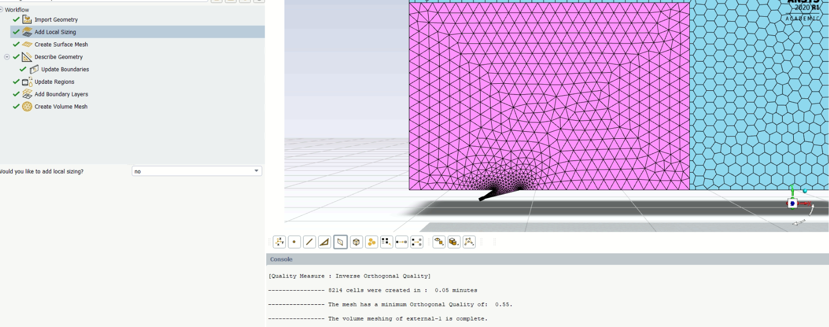
I am trying a body of influence sizing around jet region of nozzle, it does create a very good hexacore or polyhedra mesh using default settings.
The mesh I obtained using default settings (Please ignore the connections of pink and green mesh as I forgot to apply share topology)
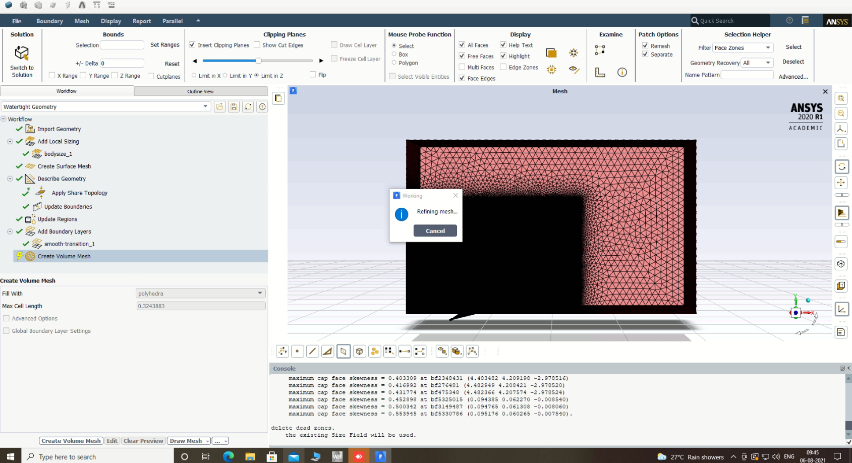
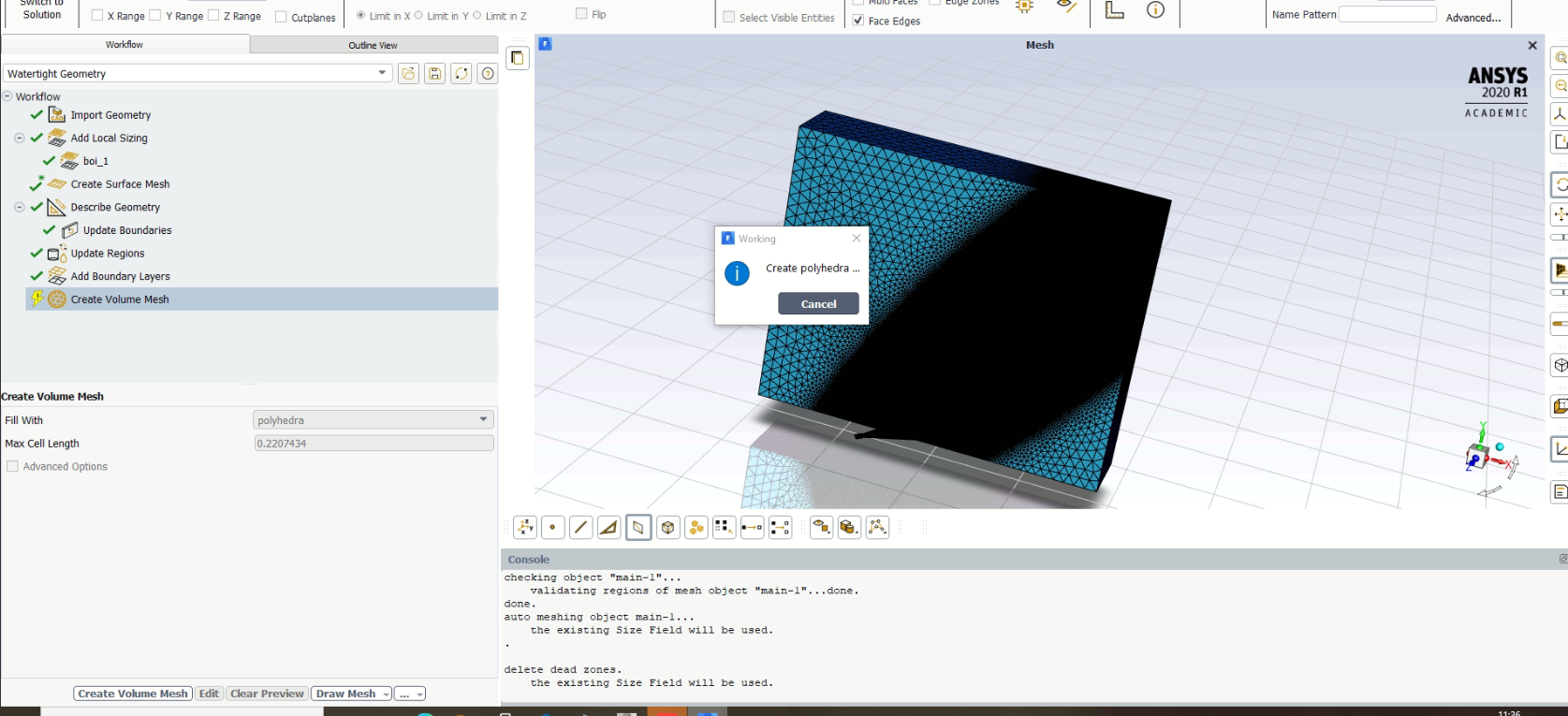
 The Mesh I obtained when I tried to refine the mesh around jet region (with local sizing of 10 mm), I don't know why but it never creates the volume mesh (I waited for around 2 hours but it shows the same message :: Refining mesh)
 I thought may be due to large domain size, so I tried using short domain but here also I am getting polyhedra mesh using default settings.
This is the mesh I obtained using body of influence with sizing of 50 mm.
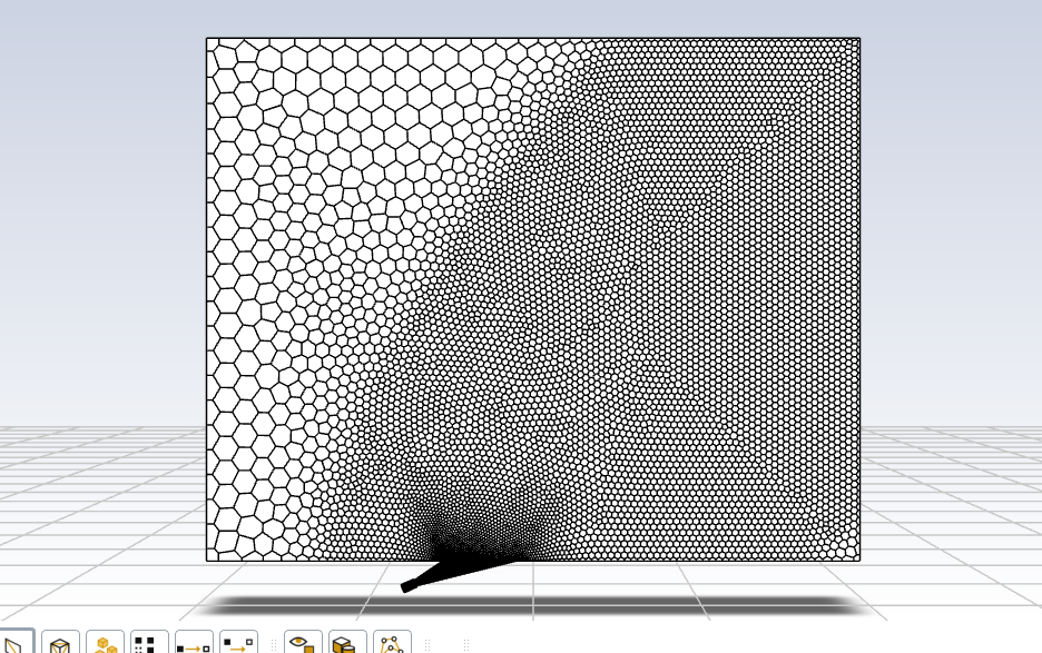 But when I try to refine it further (10mm) even for shorter domain , it never creates the volume mesh
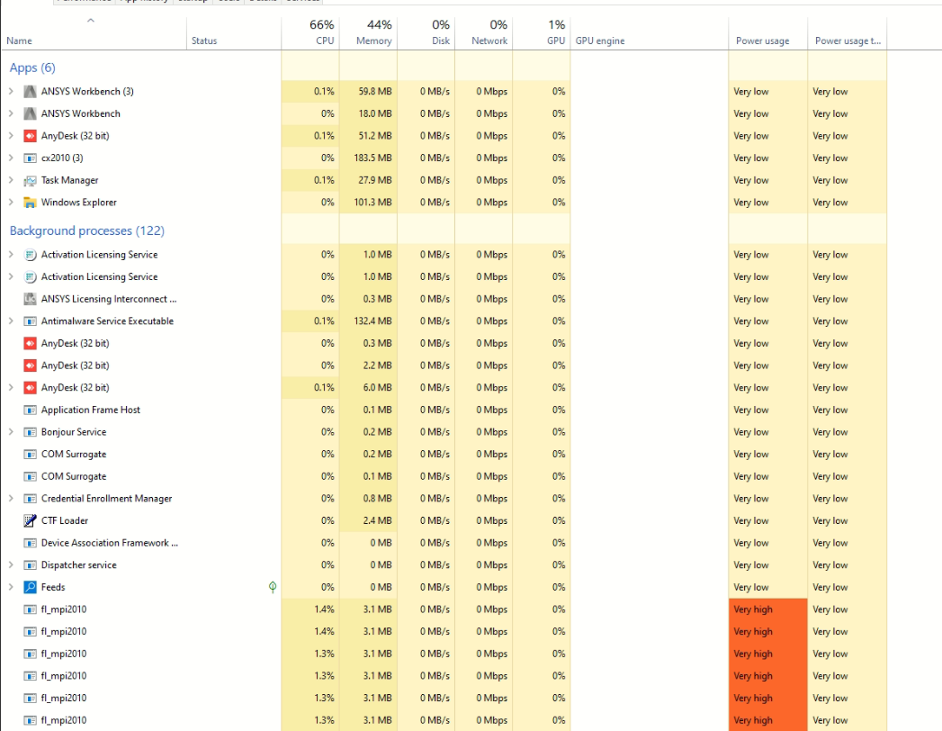
 I am using a desktop with 128 GB RAM and 48 cores and above meshing was done using 45 processors in parallel.
You can see that when I run the meshing it only consumes around 45% memory that means there is no chance of memory shortage here.
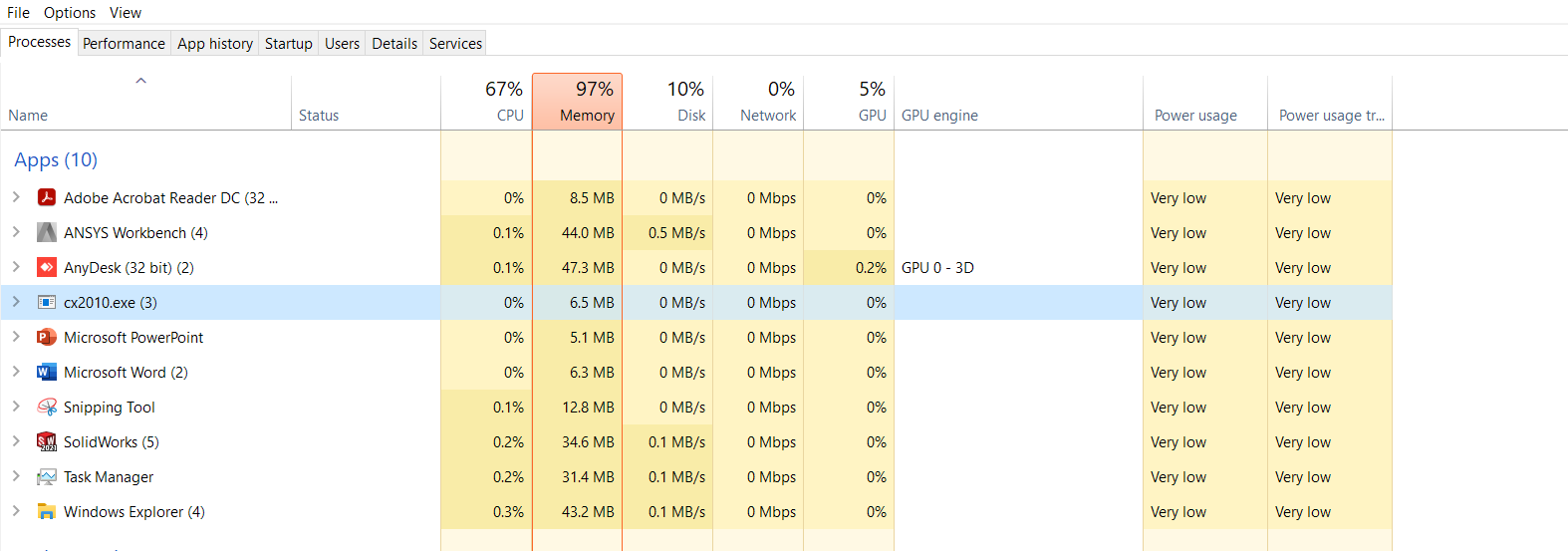
 Why I am talking about memory shortage because when I run the same meshing with 6 processors in different system with only 16 GB RAM , the meshing consumed my whole memory and I got message like Out of memory as a result in Ansys.
 I have seen a reference video from YouTube (https://www.youtube.com/watch?v=EgGNH7wqwoA&t=151s) where they are using fluent meshing on a rocket, and they are very quickly able to define body of influence sizing around 0.5mm to 1mm !!!!! . And I cannot believe that my system doesn't even produce a mesh for 10mm body of influence sizing. (I have cross verified that whether I am putting values in right units or not so that might not be the issue)
Could you tell me the reason why this is happening ?
August 6, 2021 at 9:42 amForum ModeratorCheck the domain size in Fluent Meshing. Saying you can't use 10mm cells isn't diagnostic if we don't know the size - that dimension could be too fine, or could be too coarse.
August 6, 2021 at 5:35 pmSubscriber@Rob Sir,
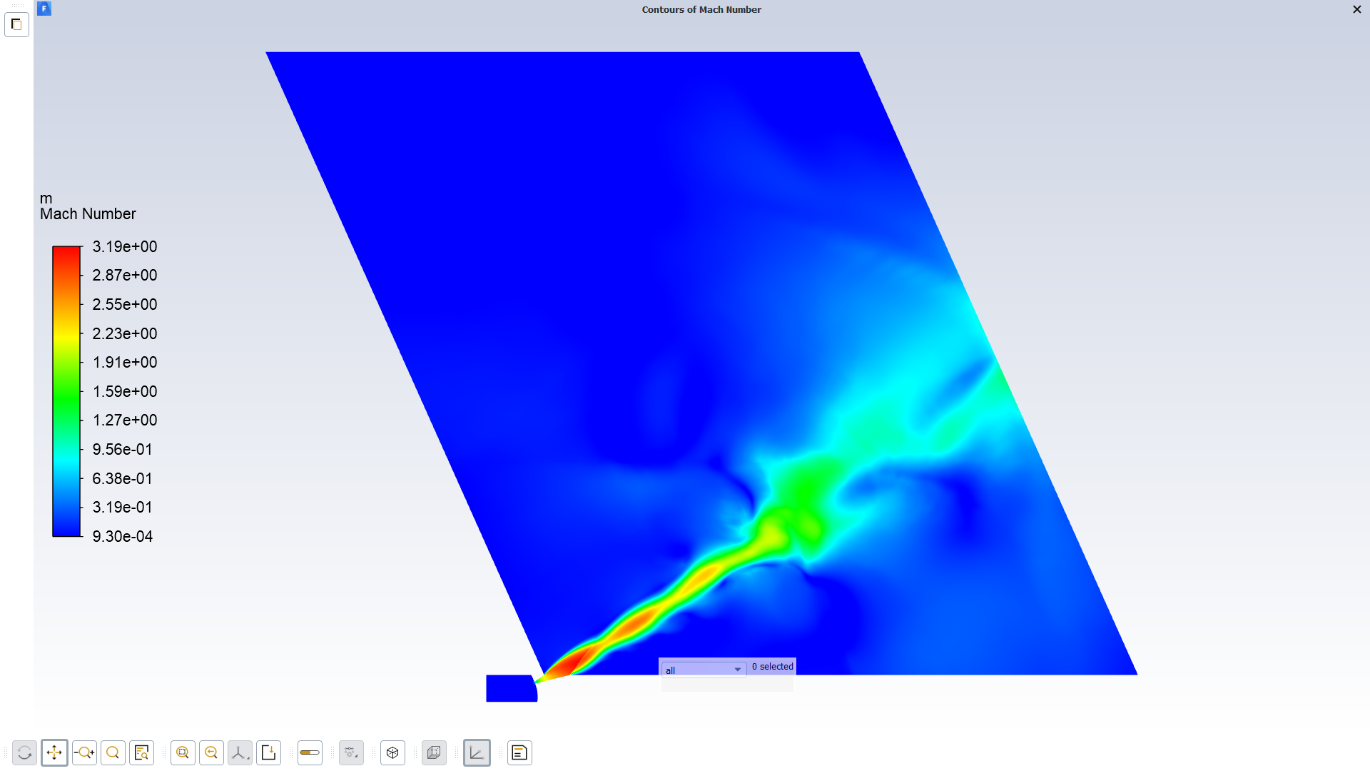
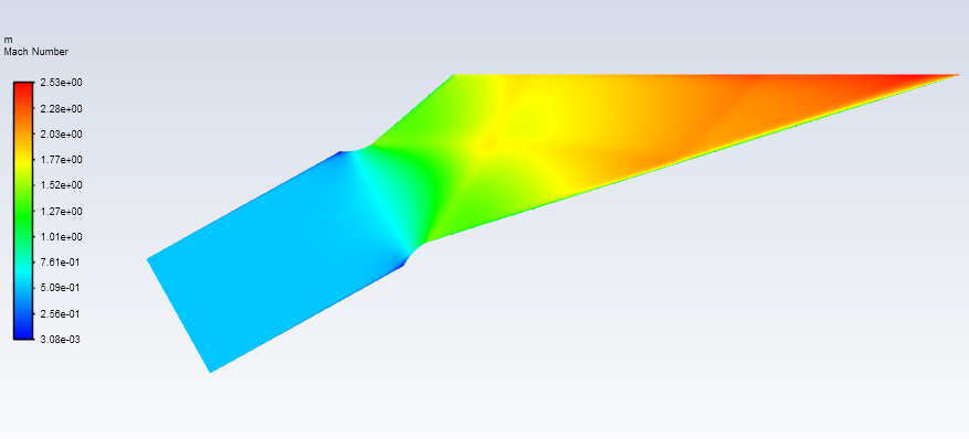
Here is my poor solution (As my residuals didn't even converge to 1e-3 and mass imbalance was in order of 2) I obtained using 2D mesh just to give an idea why I am making such a large domain due to presence of shocks or expansion waves.
(2D Domain size was 10000 mm * 6000 mm)
 Above is the image showing, How I tried to use body of influence using elliptical shape.
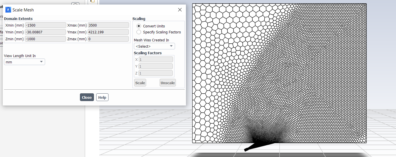
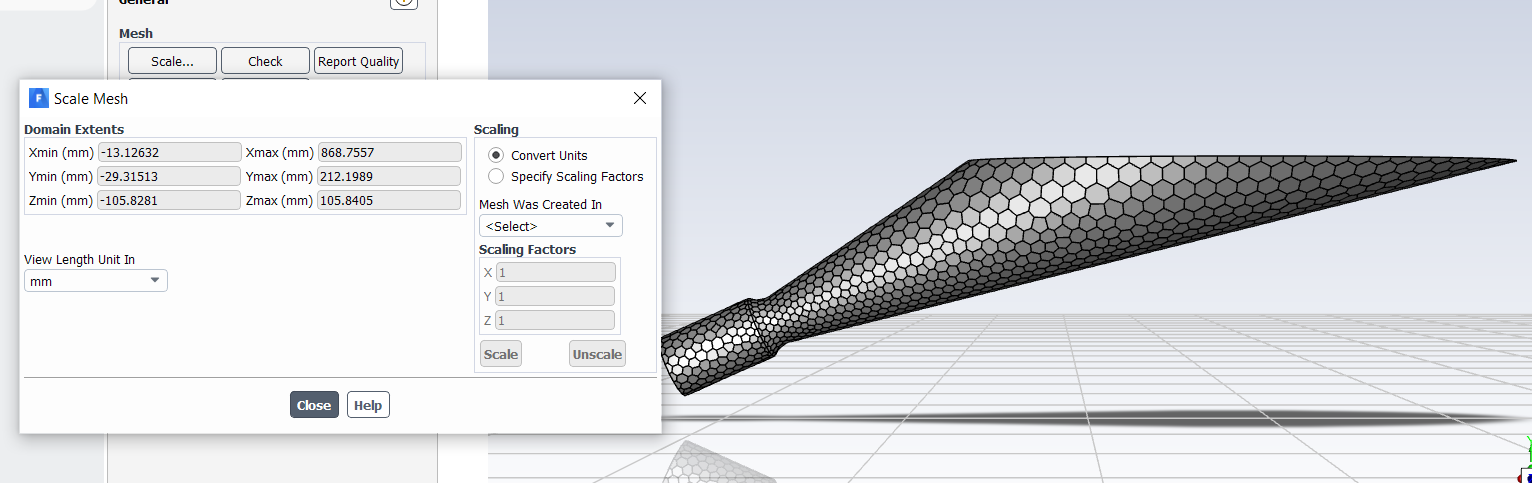 Nozzle domain extent (I didn't use scaling, I just change the view length unit in mm).
 Domain Extent for original domain using body of influence sizing of 50mm in meshing.
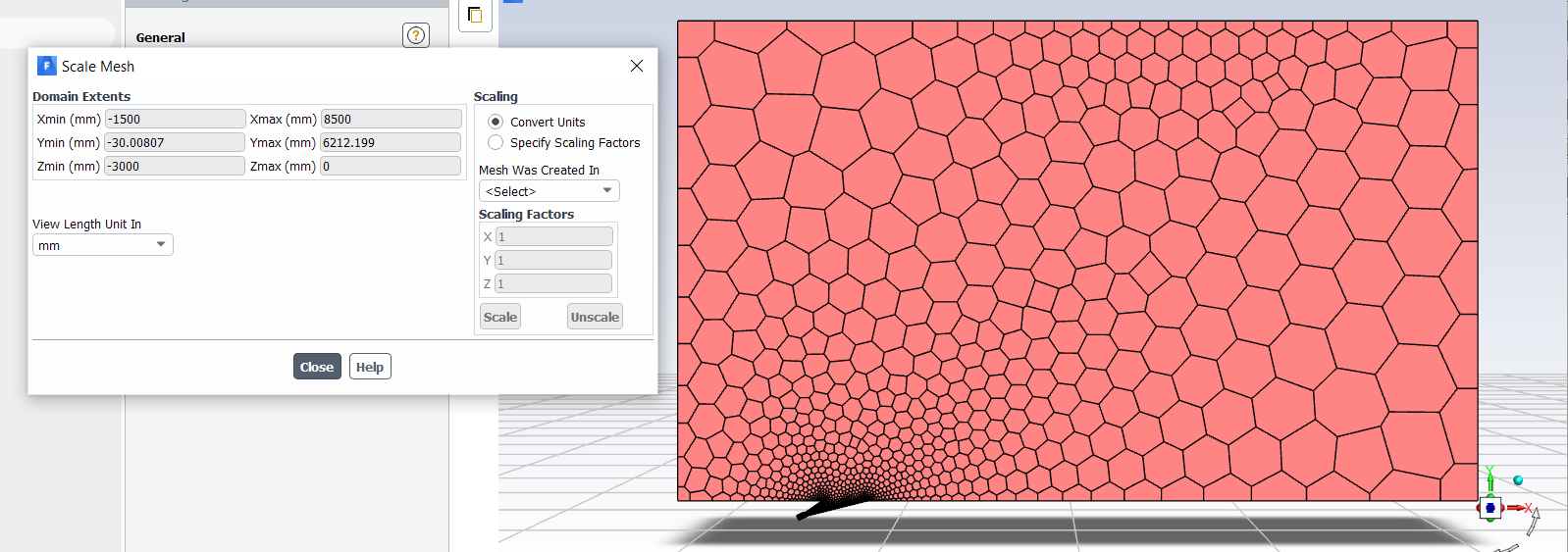
 Domain Extent for shorter domain using default settings in meshing.
I tried running my simulation for all this above coarser jet domain but residuals were not even converging in order of 3 and mass imbalance was closer to 3 or 4. That's why I think i should refine the jet region more but unable to do so.
August 6, 2021 at 5:37 pmSubscriber
August 9, 2021 at 2:51 pmForum ModeratorHave a look at the adaption tools. If you try and refine the whole region you'll run out of cells if using the Student version or cpu/RAM with the paid for versions of the solver.
August 10, 2021 at 4:51 amSubscriber@Rob Sir, I think adaption tool should be used once the solution almost converge but for my case the think is the residual blows off after some hundred iterations even for inviscid analysis
I mainly use pressure gradient and Volume change criteria but the main issue is that my residual increases after after few iteration.
I think maybe you are talking about region criteria but that also doesn't work. I don't understand for 2D Nozzle alone (with element size of 1mm) it is working fine but the moment I put a domain or convert the problem to 3D then the solution diverges.
For now I will go with 2D Nozzle alone and carry out my analysis. That's the only option I have for now given the time constraint.
Thank a lot for helping me continuously for past 2-3 weeks. It felt like I was working under your guidance, that's the amazing thing about you and this forum.
Viewing 18 reply threads- The topic ‘Doubt Regarding Unassigned Interface In Fluent’ is closed to new replies.
Innovation Space Trending discussions
 Top Contributors
-
peteroznewman
 4904
4904 -
scabo
 1598
1598 -
Dennis Chen
 1386
1386 -
javat33489
 1242
1242 -
Shyam Prasad V Atri
1021
Top Rated Tags
© 2026 Copyright ANSYS, Inc. All rights reserved.
Ansys does not support the usage of unauthorized Ansys software. Please visit www.ansys.com to obtain an official distribution.
-


The Ansys Learning Forum is a public forum. You are prohibited from providing (i) information that is confidential to You, your employer, or any third party, (ii) Personal Data or individually identifiable health information, (iii) any information that is U.S. Government Classified, Controlled Unclassified Information, International Traffic in Arms Regulators (ITAR) or Export Administration Regulators (EAR) controlled or otherwise have been determined by the United States Government or by a foreign government to require protection against unauthorized disclosure for reasons of national security, or (iv) topics or information restricted by the People's Republic of China data protection and privacy laws.


