

-
-
July 15, 2021 at 2:20 am
zhenjiehan
SubscriberHi,
I am not farmilar with mode in fiber, but why the mode feature behaves exactly the opposite as what mode in waveguide?
The feature of fundamnetal TM mode in fiber behaves similarly as fundamental TE mode in waveguide, the feature of fundamental TE mode in fiber behaves similarly as fundamenatl TM mode in waveguide.
July 15, 2021 at 8:41 pmGuilin Sun
Ansys EmployeeAs you may know, different waveguide/fiber can support different types of modes. I would suggest you
1: copy the structure into MODE's FDE and check the mode property;
2: download online example and check its mode property.
Please note that in y direction it has used anti-symmetry BC to pick up the specific modes with that symmetry property. So the "fundamental" is actually not that fundamental when no symmetry BC is applied. The result showing "Fundamental TE" is 2nd order mode.
July 16, 2021 at 9:03 amSubscriberThank you for your respond.
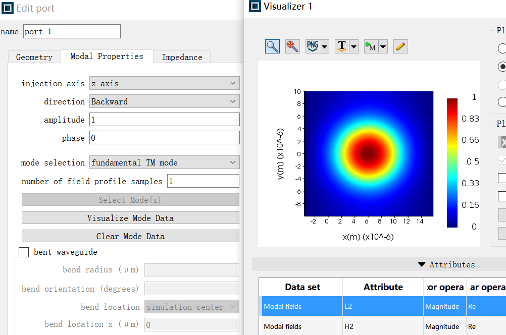
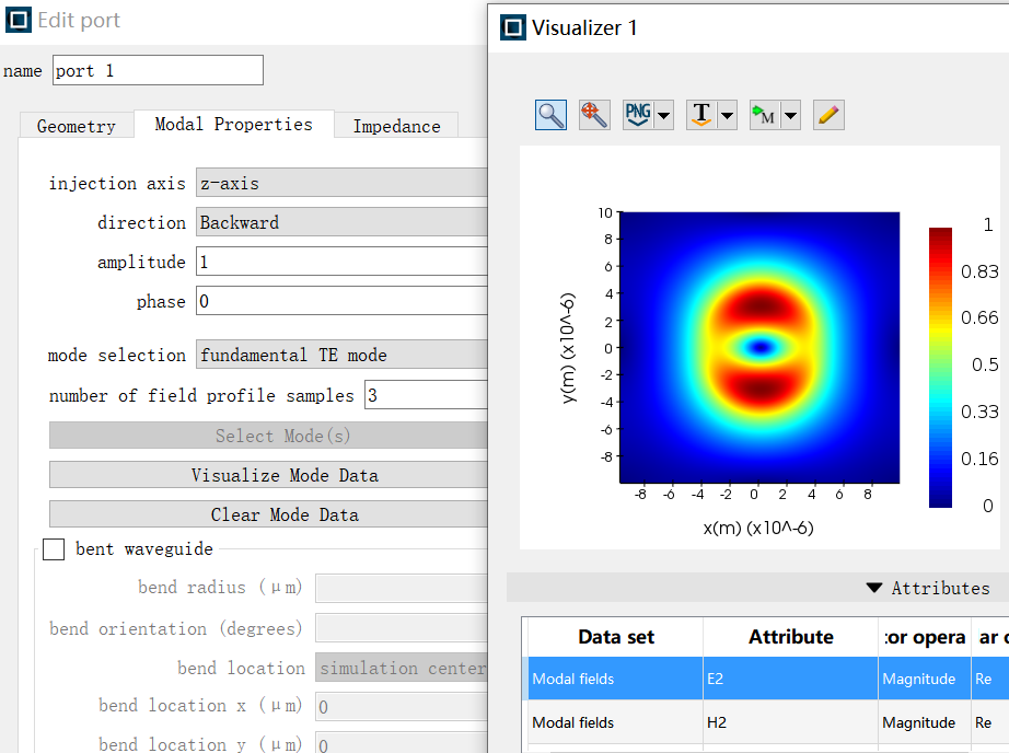
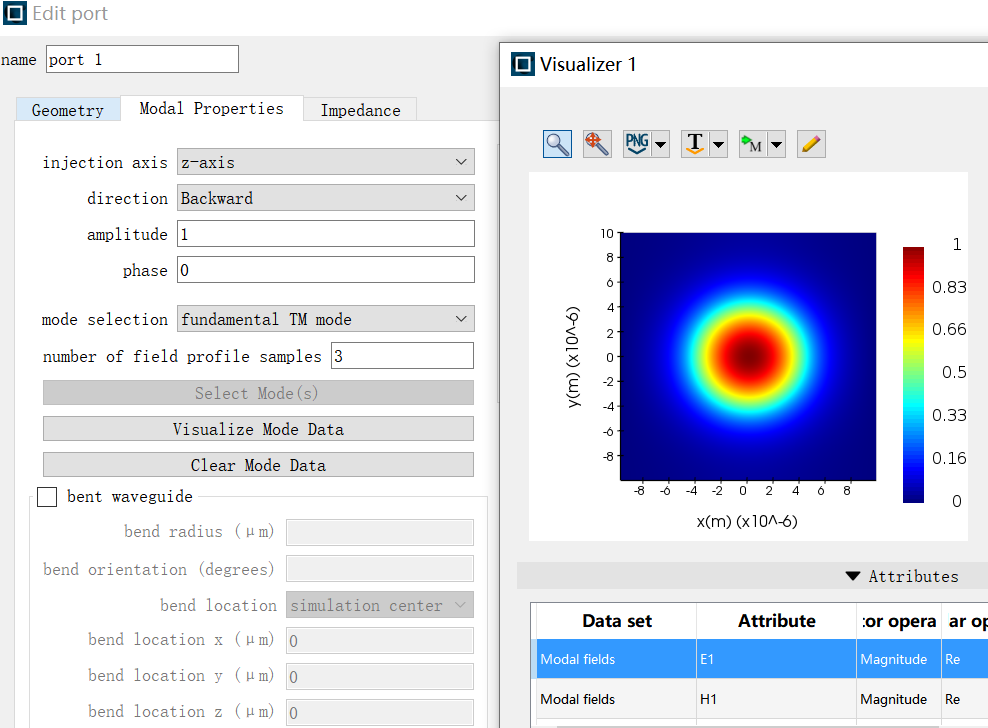
If I change boundary to "PML", then select fundamental TE mode, it shows like this:
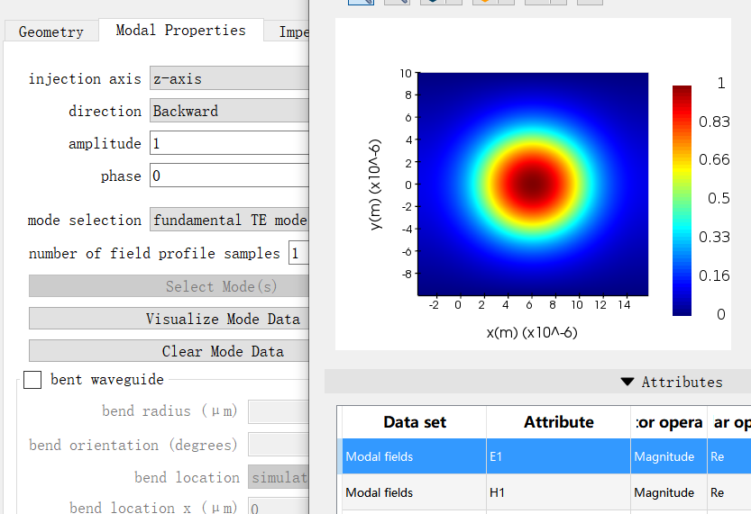
if I select fundamental TM mode, it shows like this:
For the first method you provide:
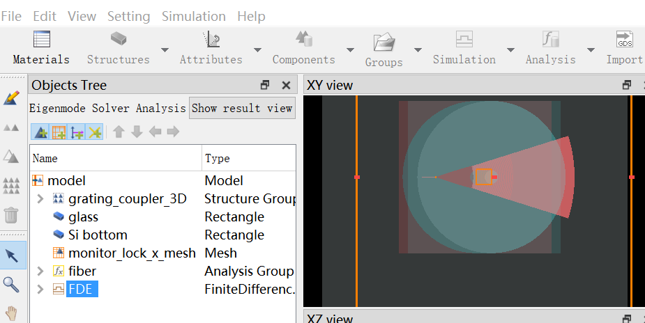
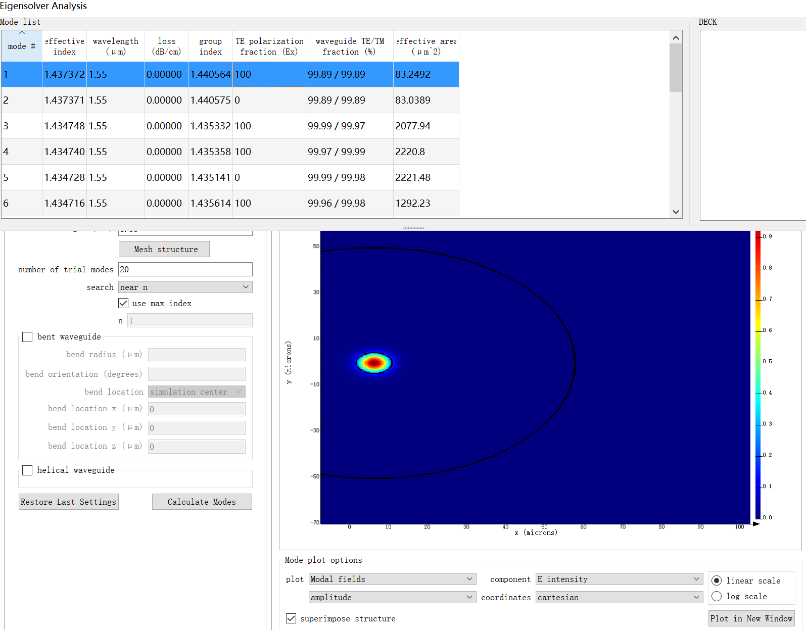
I have copied the geometry into MODE,and I get something like this:
 The following is the situation when z direction of FDE is in waveguide:
 The following is the situation when z direction of FDE is in fiber:
For the second method you provide:
In example of "360042305334-grating-coupler.zip" and "360042800573-inverse-design-of-grating-coupler", the fundamental TE and fundamental TM mode shows like this:
I am still confused with this,could you give me some more cclearer suggestion?
For a common fiber, with core diameter equal to 9um, clad diameter equal to125um, what should the fundamental TE and TM mode in fiber look like?
July 16, 2021 at 3:06 pmAnsys EmployeeI should say that the word "fundamental" in the software may not be fundamental when symmetry BC is used. In text book, the fundamental modes are the first TE and TM modes. However, when symmetry BC is used, one of the true fundamental mode is suppressed. But, the software just uses "fundamental" for the higher order mode with other polarization. It is not smart enough.
You can compare the result by use of symmetry and no symmetry BC and compare their properties, in particular the polarization.
For the fiber, since it is circular, fundamental TE and TM modes have about the same neff and intensity but different polarization. The intensity profiles have a peak at the center.
July 30, 2021 at 6:05 amSubscriberThank you very much for your respond.
I still have another 3 questions.
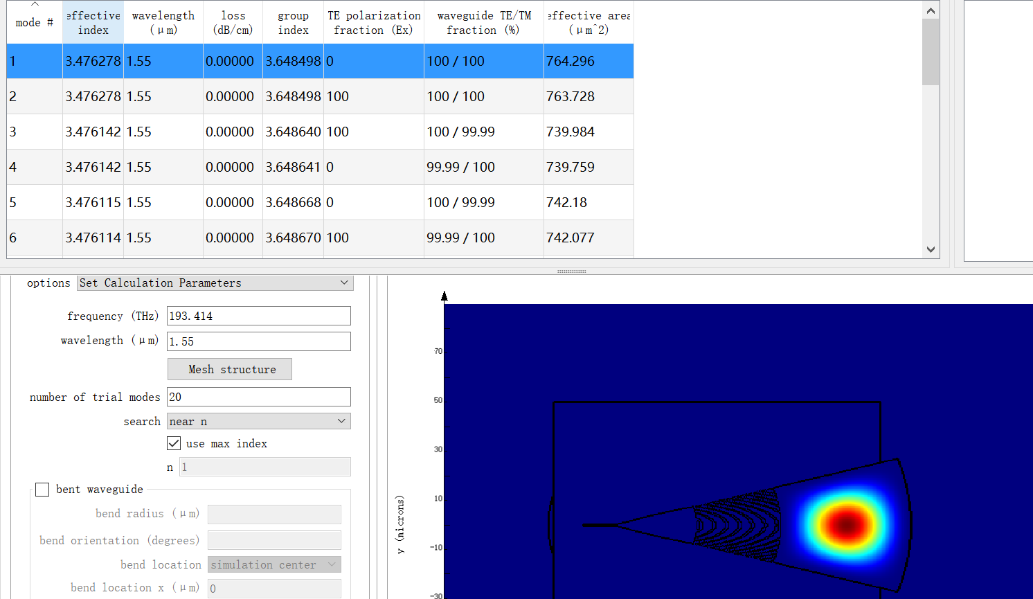
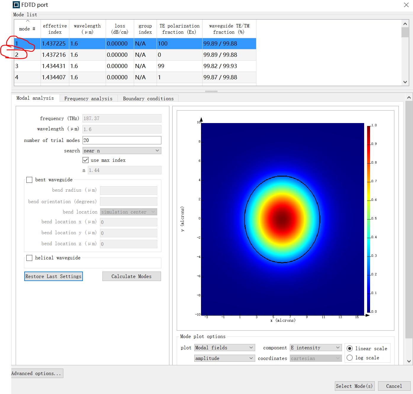
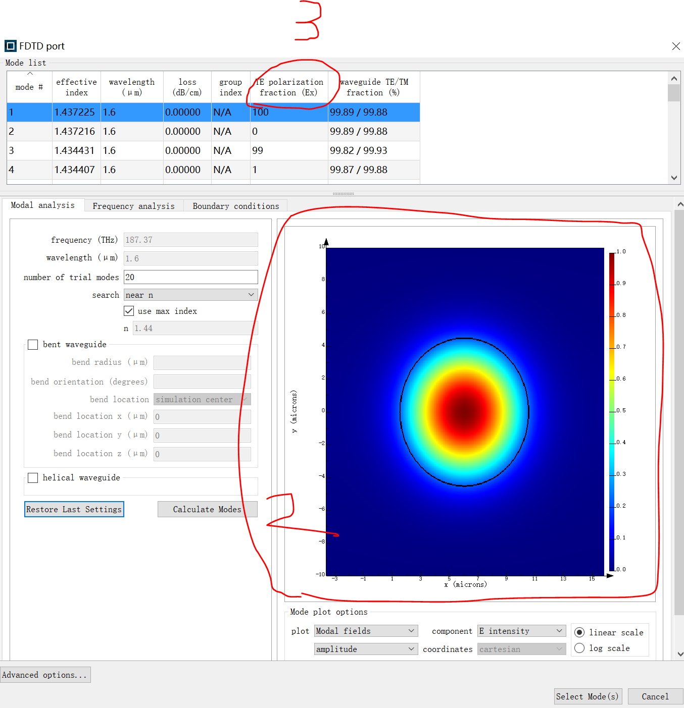
1.Setting the boundary to PML, which have no symmetry BC, I got modes like this, can I think that mode 1 (neff= 1.437225, TE polarization fraction=100%) is fundamental TE mode, mode 2 is fundamental TM mode?
2 You said, the fundamental mode of TE and TM for fiber have the same neff and intensity, but have different polarization.
Does the intensity mean the fiture here(2)?
Then, how to tell which are TE modes, which are TM modes?
Does TE polarization fraction (3) geater than 1% mean it is TE mode? Does TE polarization fraction equal to 0 mean it is TM mode?
3.I find in the download example of "grating coupler", the mode by "user select" for PML and "anti-symetric" BC is different. It seems that the mode by "anti-symetric" is wrong, then why use anti-symetric BC in grating coupler example?
For PML BC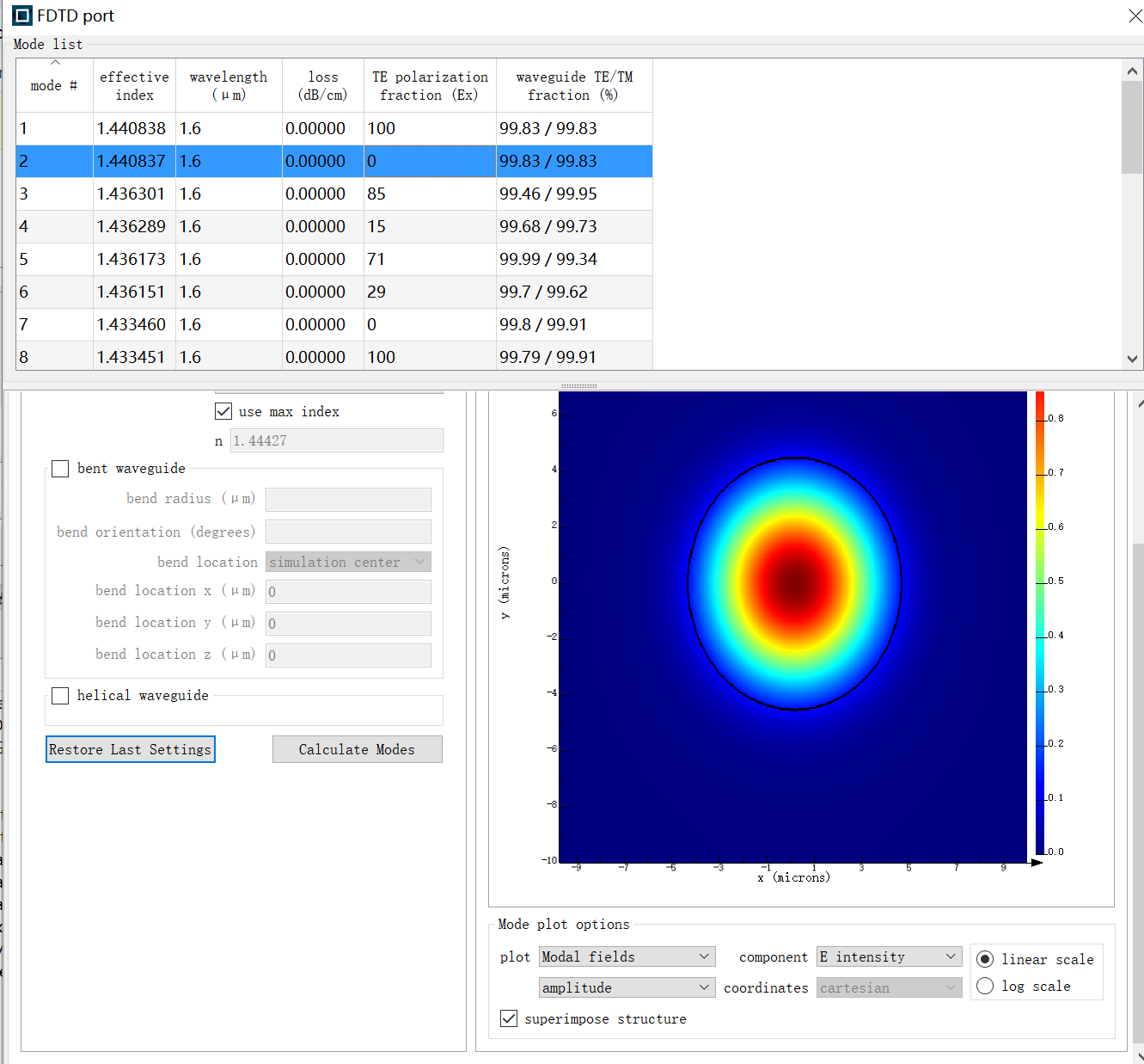
For "anti-symetric" BC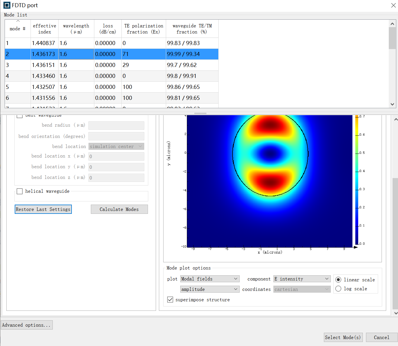
July 30, 2021 at 4:31 pmAnsys EmployeeA1: yes, you can. due to numerical error, their neff is slightly different; A2: For TE fraction, please refer this page: https://support.lumerical.com/hc/en-us/articles/360034396734-FDE-solver-analysis-Mode-List-and-Deck BTW: I also refer you to this post: Ansys Insight: 有关TE、TM模式以及模式光源的问题 For for contrast waveguide, traditional definition may not well fit. So please check the dominant field component. A3: it is not wrong. In this case, you should not count the mode number to determine if it is TE or TM. You should check the dominant field component instead. When symmetry BC is used, it will suppress the other polarization. Once you get more information from #2, you will know why.Viewing 5 reply threads- The topic ‘Why fundamental TE mode in fiber behaves like fundamental TE mode in waveguide?’ is closed to new replies.
Innovation Space Trending discussions
 Top Contributors
-
peteroznewman
 6104
6104 -
scabo
 1906
1906 -
Dennis Chen
 1436
1436 -
javat33489
 1308
1308 -
Shyam Prasad V Atri
1021
Top Rated Tags
© 2026 Copyright ANSYS, Inc. All rights reserved.
Ansys does not support the usage of unauthorized Ansys software. Please visit www.ansys.com to obtain an official distribution.
-


The Ansys Learning Forum is a public forum. You are prohibited from providing (i) information that is confidential to You, your employer, or any third party, (ii) Personal Data or individually identifiable health information, (iii) any information that is U.S. Government Classified, Controlled Unclassified Information, International Traffic in Arms Regulators (ITAR) or Export Administration Regulators (EAR) controlled or otherwise have been determined by the United States Government or by a foreign government to require protection against unauthorized disclosure for reasons of national security, or (iv) topics or information restricted by the People's Republic of China data protection and privacy laws.
