-
-
June 28, 2021 at 10:55 am
vishal295
SubscriberHallo,
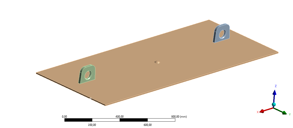
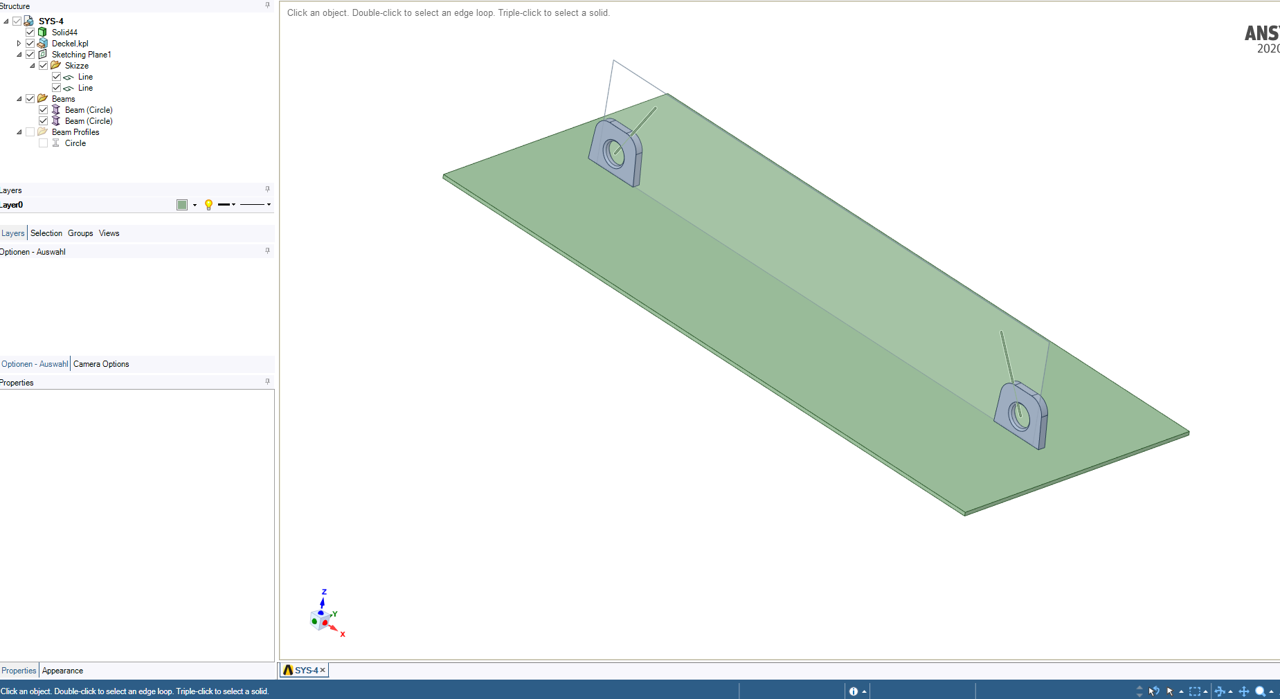
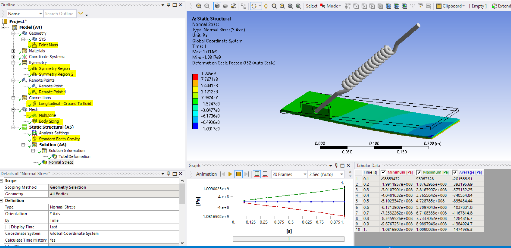
I am doing structural simulation of a cover plate. I have a cover plate with two lifting lugs attached on the top (as shown in figure) and 4000 kg of mass is attached at the bottom of the cover plate (which I took as point mass in model). This lifting lugs (holding cover plate with 4000 kg weight) is lifted by crain in Z axis. I want to see the bending at the cover plate.
For which I have considered the ''Remote displacement boundary condition on edge of the cover plate (I cannot take fixed boundary condition because it is not fixed) further more I have tried to add stiffenes on the wall but it is not stable.
Can anyone suggest me which boundary condition I need to consider ?
p.s.- I have theoretical result and practical result, which is quite similar, whihc is around 80mm deformation at middle of the plate due to lifting.
cover plate dimensions are 1750mm*720mm * 10mm thickness.
Thank you !
Best regards,
Vishal
June 28, 2021 at 11:41 amErKo
Ansys EmployeeHi
Try two remote displacements, so one for each lug (scoped to the inside lug face) - for both, restrain all translations (X,Y,Z =0) and rotations about X (=0).
The try to solve with a smaller mass - say 1 kg to see that the system is balanced and can solve.
When it does, include large deflections (ON), and run with the full weight - set substeps : /forum/discussion/9325/substeps
Also include an image in the next post so we can see how the structure is supported.
Thank you
Erik
June 29, 2021 at 11:25 amSubscriberErik
Thank you for the reply.
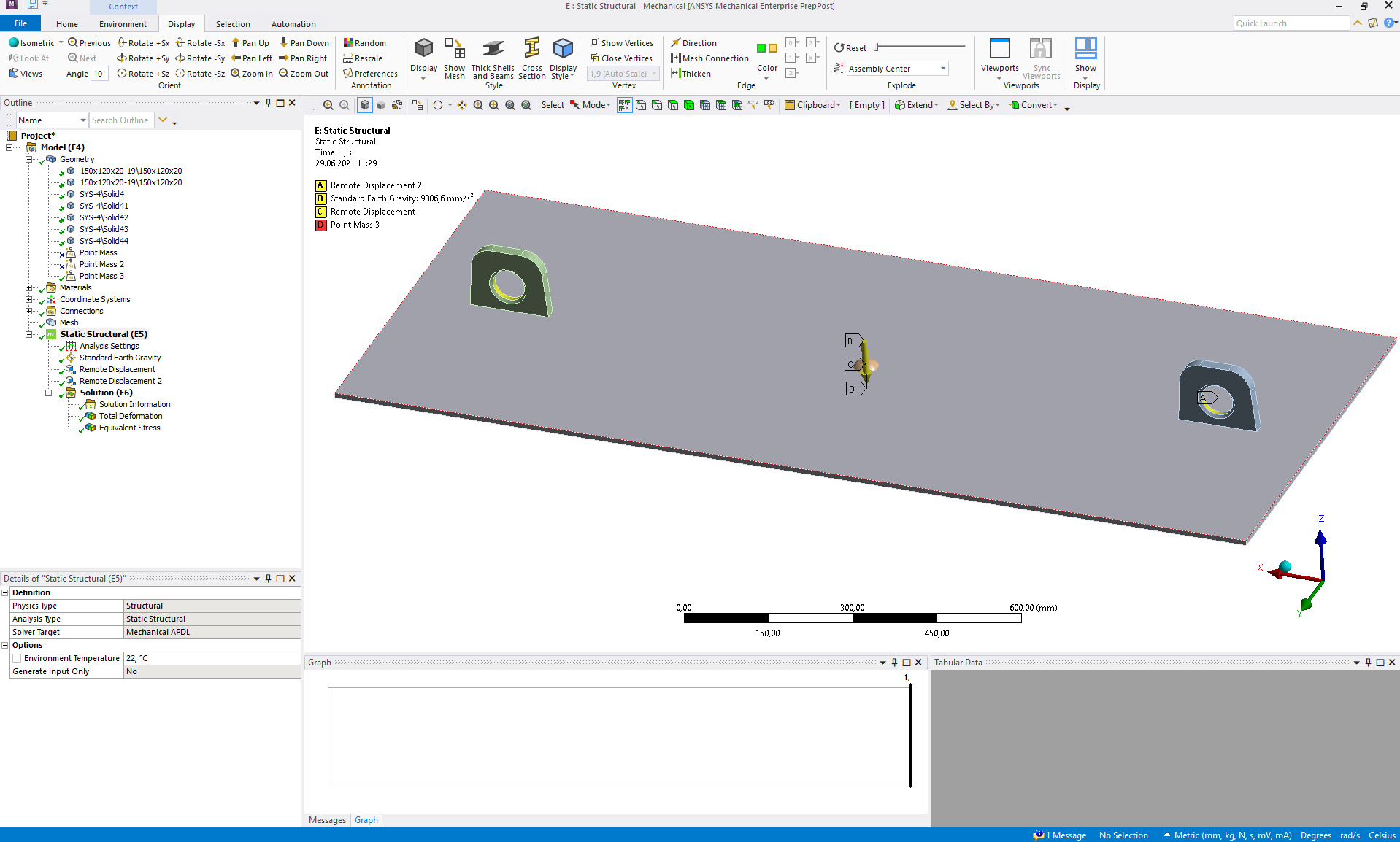
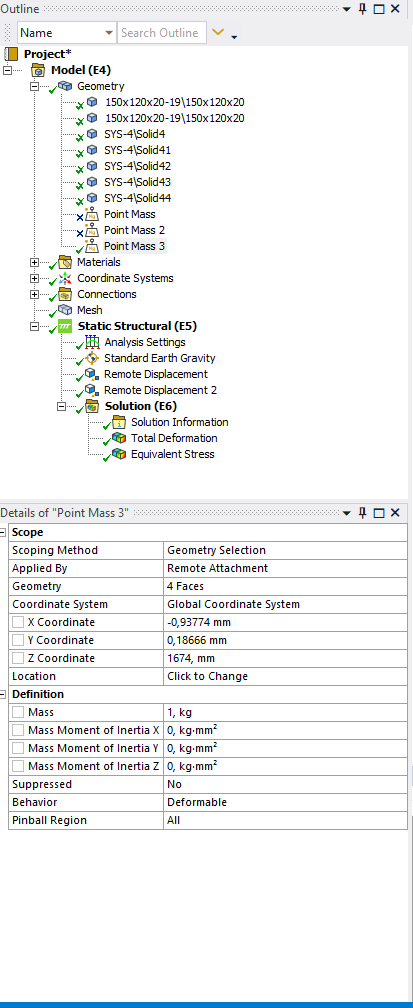
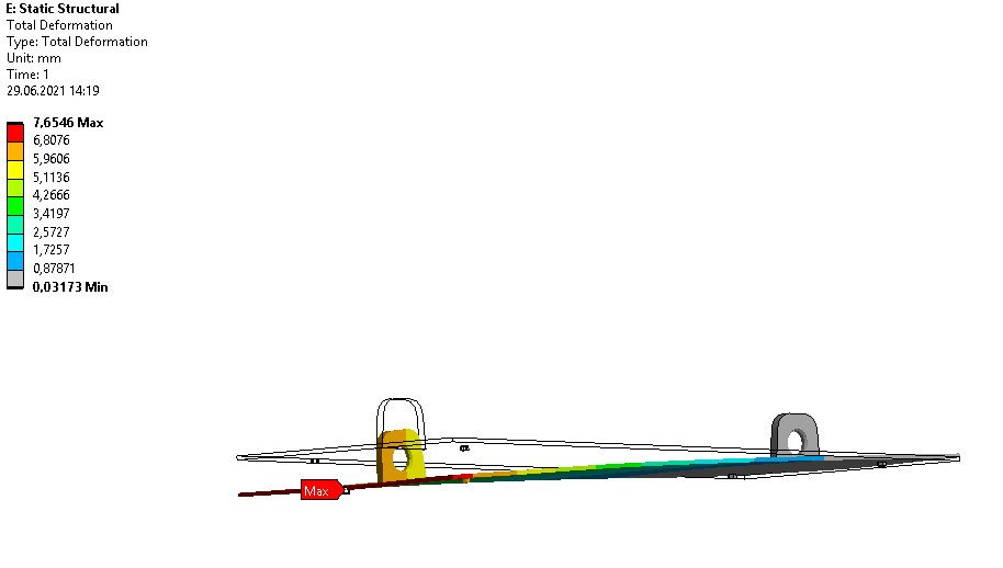
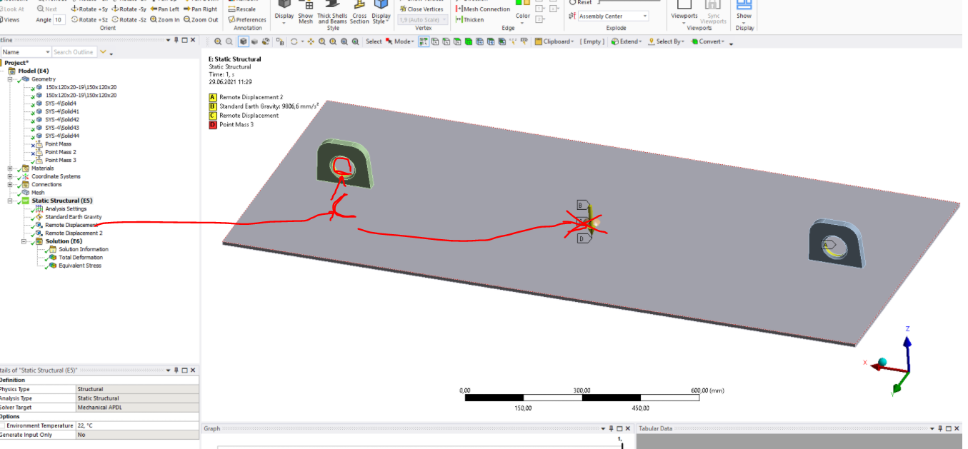
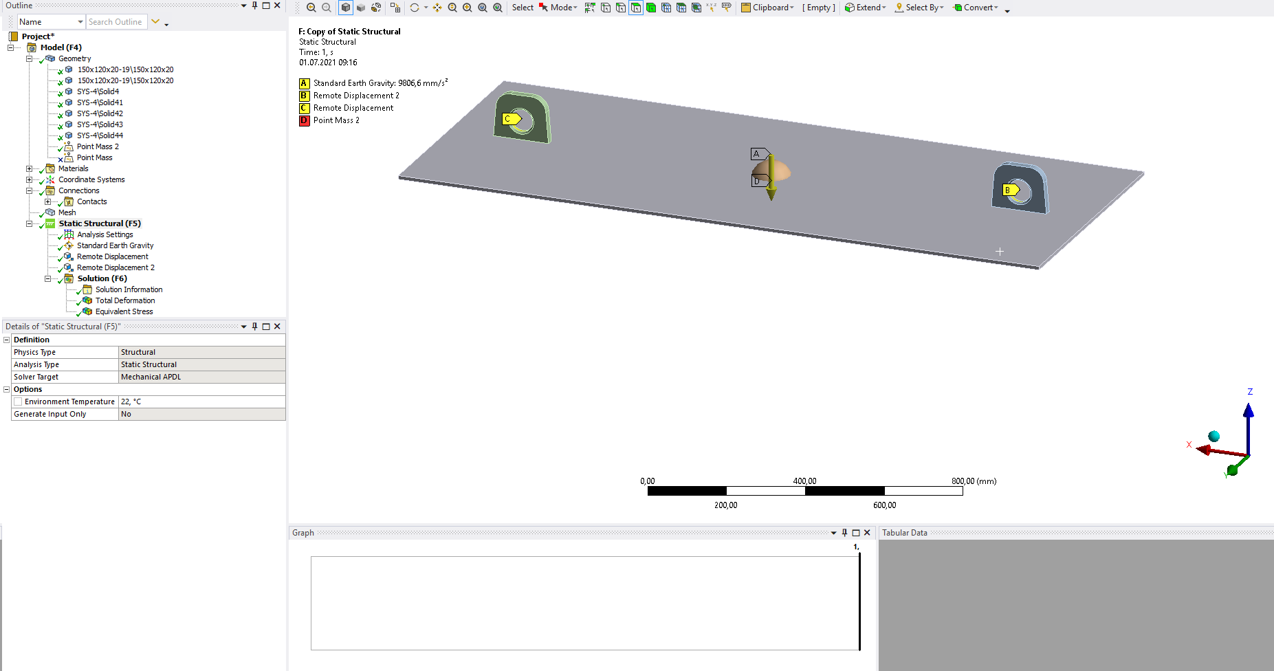
I tried approach related to remote displacement, (in attached picture you can the boundary conditions ).
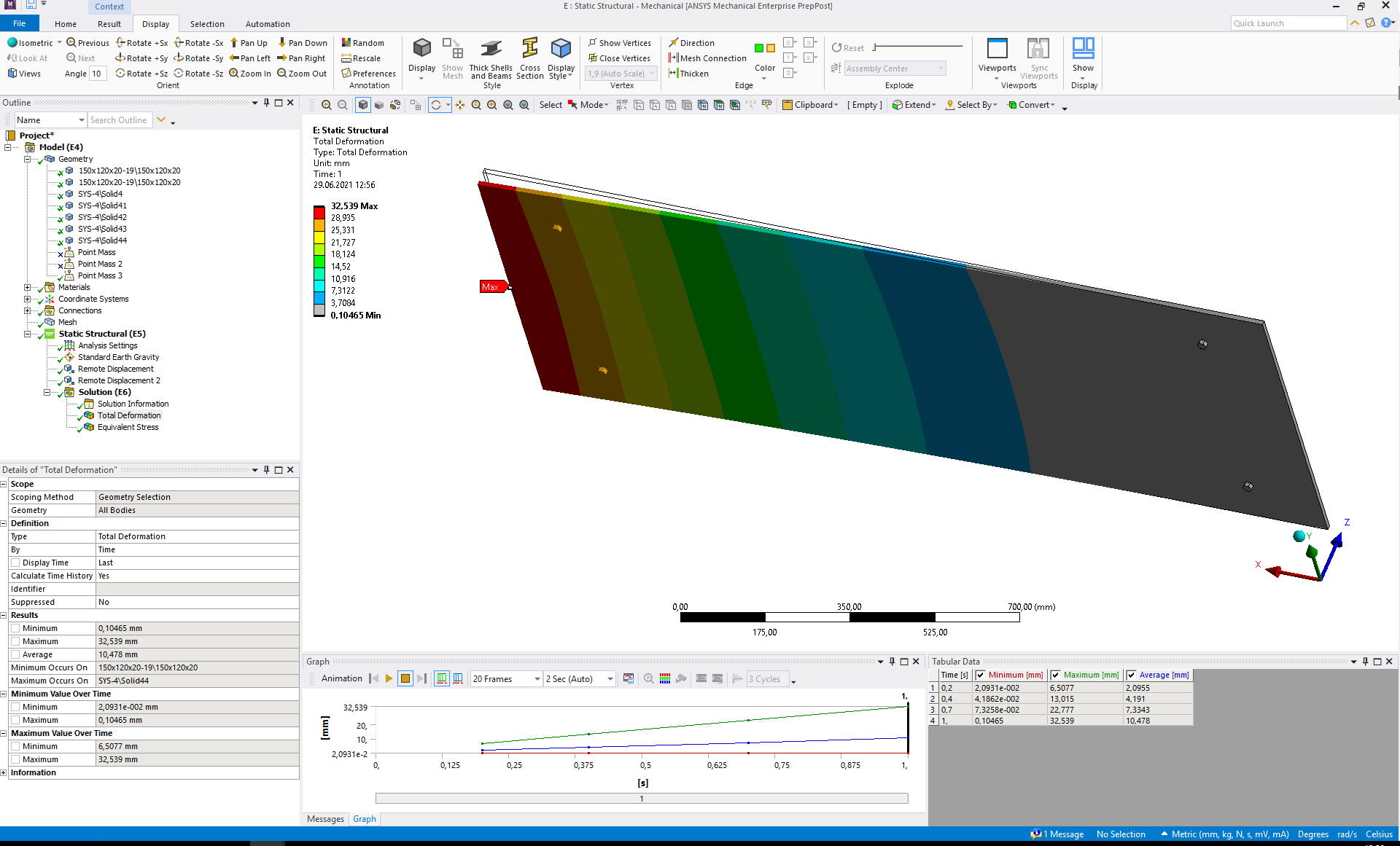
I have applied 2 remote displacement to each lifting lug inner surface with (X,Y,Z displacements to zero and rotation about X=0) and considered point mass 1kg with large defletion OFF. But in this case I am getting unbalanced deformation (in attached picture). My geometry is symmetric. I don't understand why is it so ??
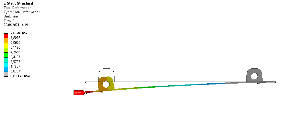
In reality Cover plate is deforming high in the middle (not at the corner) and lifting in reality is at some angle (in picture first picture) (This reality simulation I would do with ''Link180 element''- But I am looking for some tutorial related to this).
Thank you!
Best regards Vishal

June 29, 2021 at 11:46 amAnsys EmployeeHi
Can we see the results from different views please.
Also set the remote displ. behaviour to rigid, and also for the point mass.
Thanks
Erik
June 29, 2021 at 12:22 pmSubscriberHi Erik
I have set remote displacement behaviour to RIGID and for point mass also RIGID.
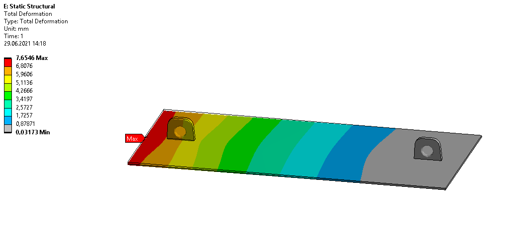
Results from different views are in attachement.
BR Vishal
June 29, 2021 at 1:35 pmAnsys EmployeeHi
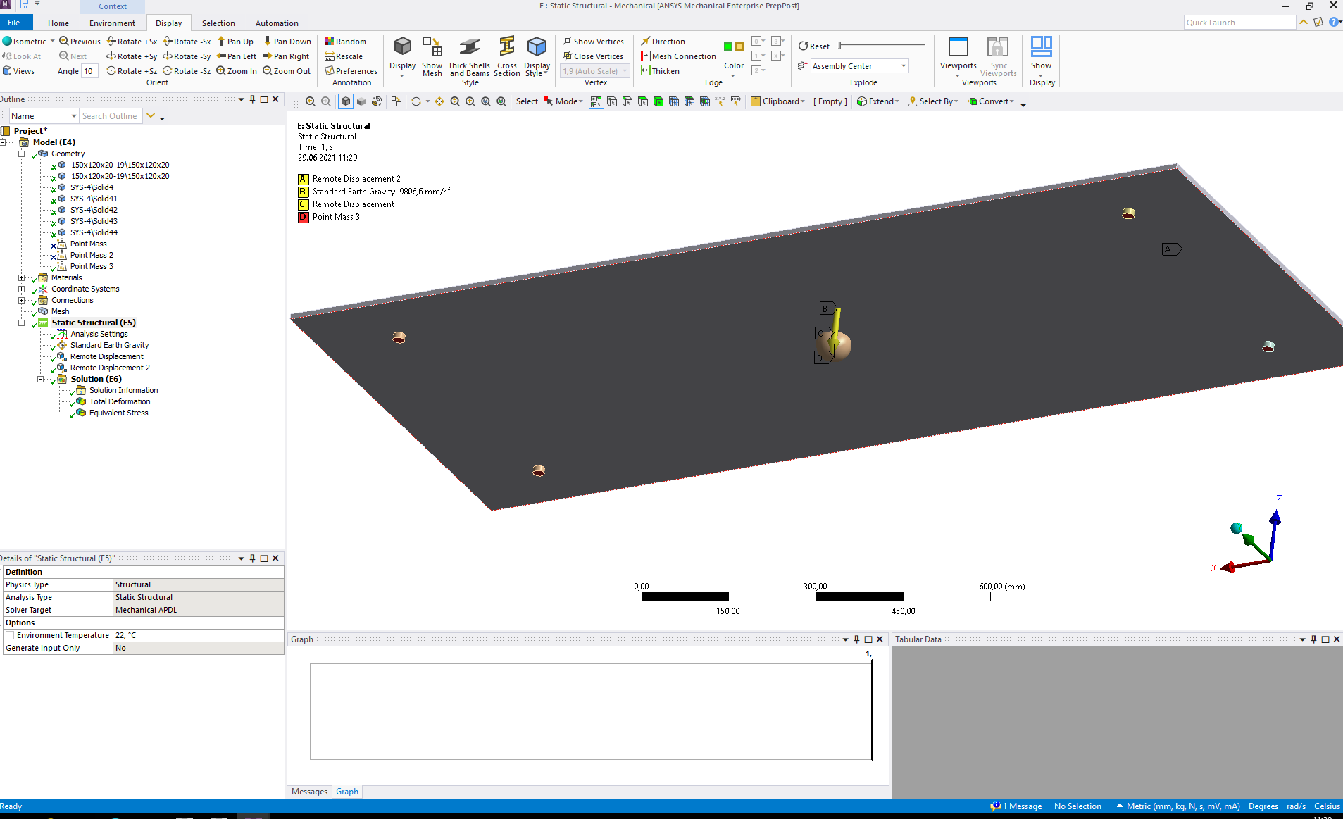
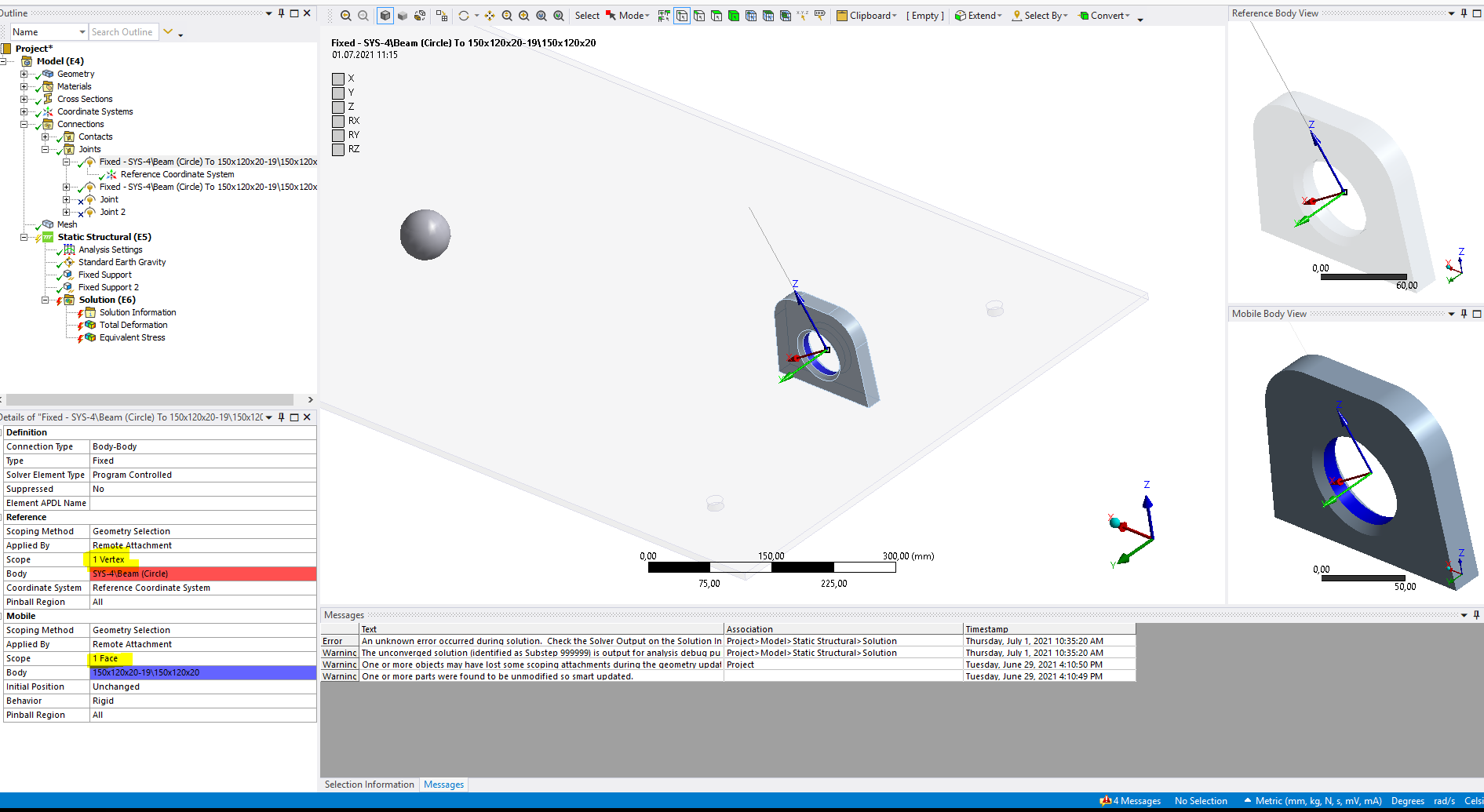
As we can see the left boundary condition (C in the image below) is not working, as that lug moves in the z direction so downwards.
So on one of the remote displacements (C in the image below) on this left lug is wrongly scoped. Make sure that remote displacement (C below) is scoped to the inside face of this left lug (lug that moves down), just as marked below.
 Also for the point mass, scope as direct attachment, and to a node or introduce a vertex and scope it to that point/vertex.
Thank you
Erik
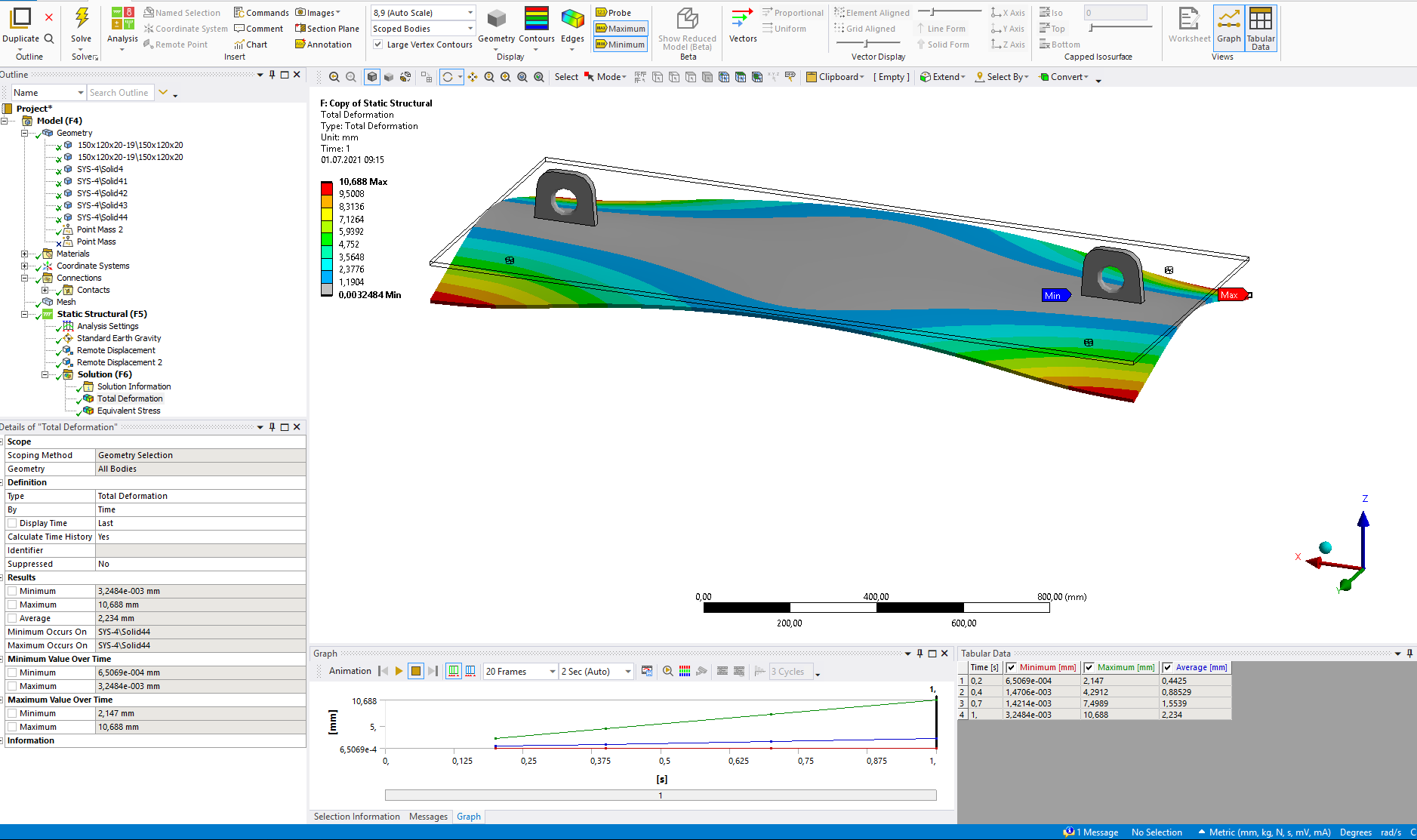
July 1, 2021 at 9:25 amSubscriberHi Erik Thank you.
Exactly, as you mentioned in last comment remote displacement boundary condition at C was not correct (coordinates were not correct, surface was true).
Coordinates were different. I have selected the true surface. I don't know why coordinates were different but Now I have corrected it ! And after 1kg point mass with large deflection off, I got symmetric deformation as expected. And even after increasing the point mass to somewhat reality and with large deflection on, I got reasonable result deformation.
now I am getting symmetric deformation with this remote displacement at lifting lugs inside surface boundary condition.
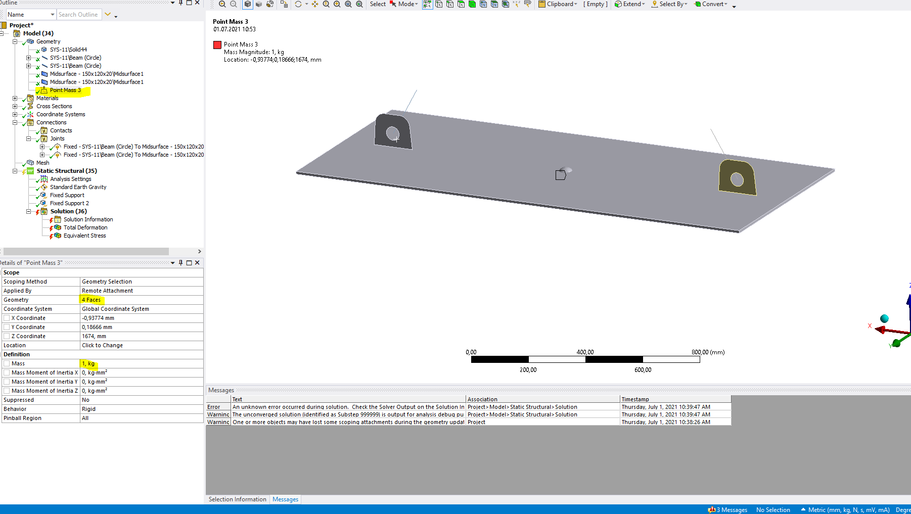
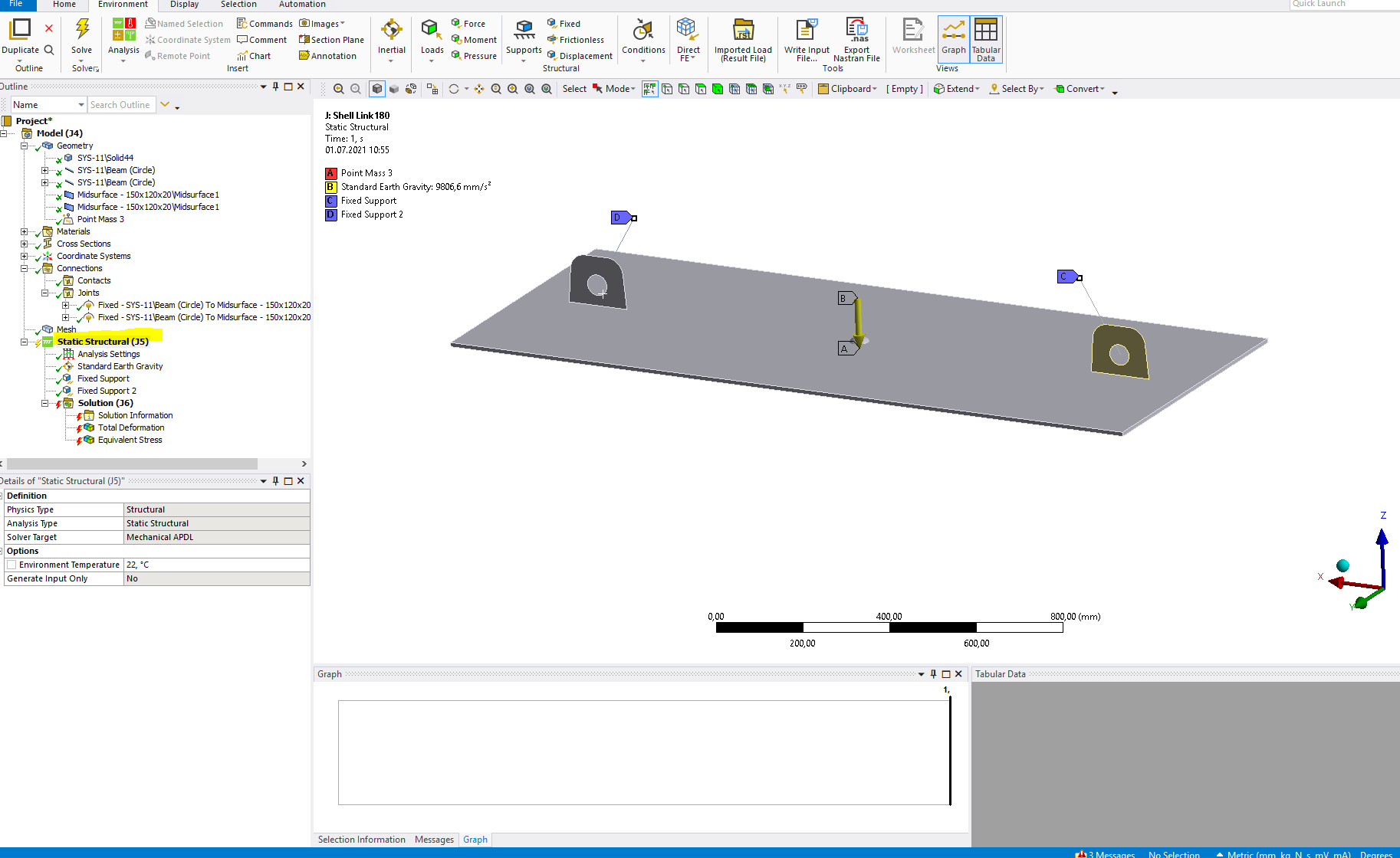
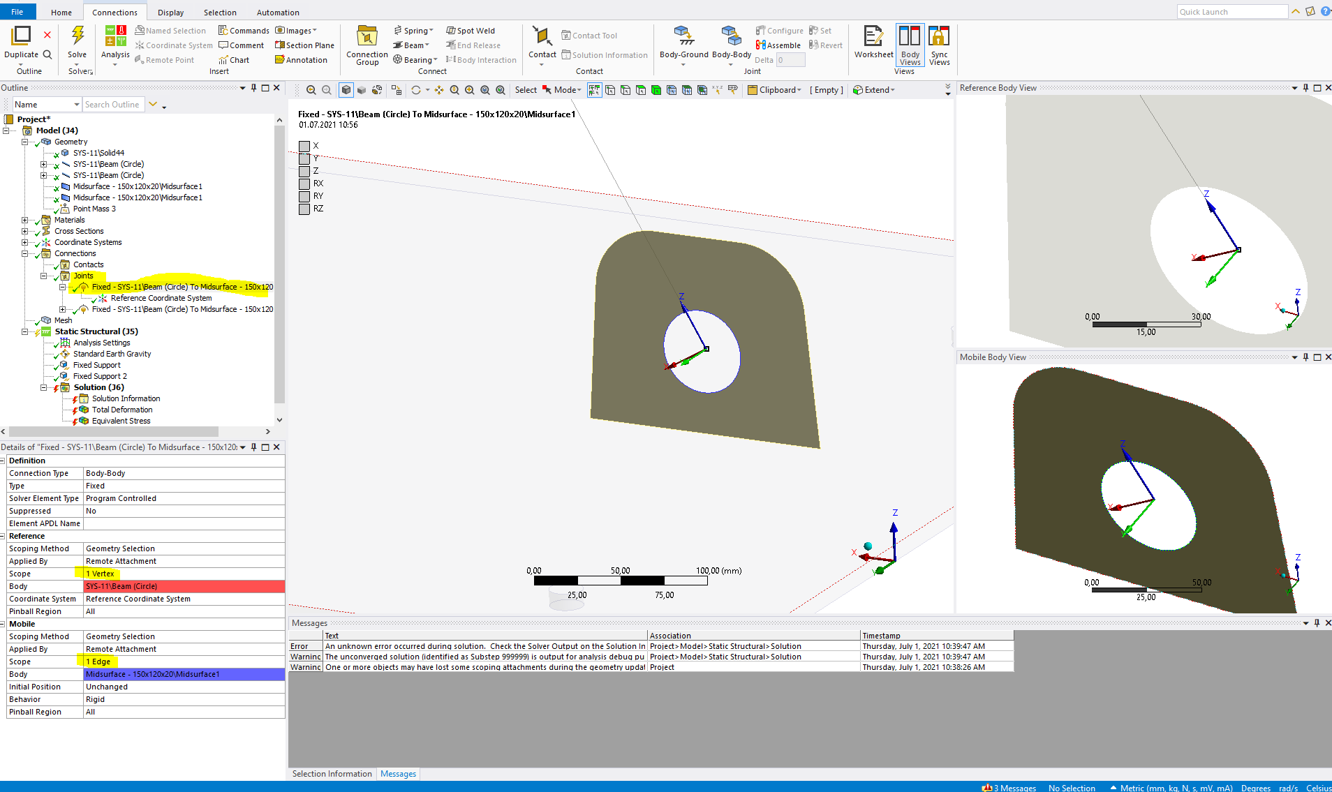
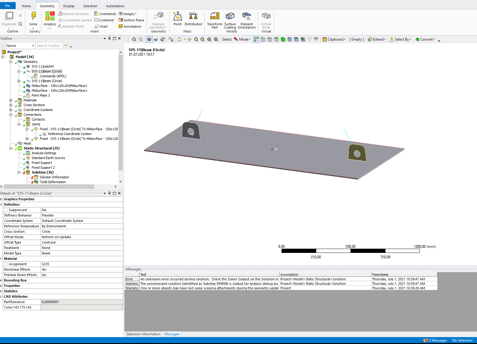
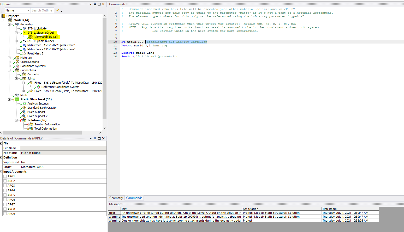
But when tried to use LINK180 to give more accurate boundary condition (like in picture) (because in reality is hanged by chain at some angle).
I have this settings as in attachment for LINK180. Is there any tutorial or video or discussion about this ?
I have created the rope/chain in spaceclaim. I applied Boundary condition as in attached pictures. I am getting some error. Can you please help me with this ???
Should I open new discussion for this or is it ok if I discuss here.
BR Vishal
July 1, 2021 at 9:26 amSubscriber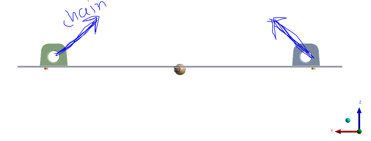
July 1, 2021 at 10:10 amAnsys EmployeeHi
This is quite tricky - look on other posts and search to find some solution:
One search gave this:
Also I would use quarter symmetry (as shown below) and spring instead of link180 (they do the same thing here in this case - as shown below) to get balance and to get convergence since a full model on ropes/chains/slings is not stable.
Viewing 8 reply threads- The topic ‘Boundary conditions_Add Stiffeness’ is closed to new replies.
Innovation Space Trending discussions
 Top Contributors
-
peteroznewman
 5669
5669 -
scabo
 1890
1890 -
Dennis Chen
 1419
1419 -
javat33489
 1304
1304 -
Shyam Prasad V Atri
1021
Top Rated Tags
© 2026 Copyright ANSYS, Inc. All rights reserved.
Ansys does not support the usage of unauthorized Ansys software. Please visit www.ansys.com to obtain an official distribution.
-
Ansys Assistant will be unavailable on the Learning Forum starting January 30. An upgraded version is coming soon. We apologize for any inconvenience and appreciate your patience. Stay tuned for updates.