TAGGED: boundary-conditions, meshing, modal-analysis, natural-frequency, spring
-
-
June 16, 2021 at 6:42 pm
ahmadsamih1
Subscriberi am doing my project using a multi leaf spring. I have done modal analysis to obtain the natural frequency, and i also have done an accurate theoretical calculation to find the natural frequency for first four modes. my issue is that the percentage of difference is very high when i compare theoretical results to FEM ansys results. I am not sure what causes the high percentage difference. i have followed the boundary conditions exactly. but cant get less than 10% percentage of difference most is 30% and more. what might affect my FEM simulation results. for meshing i have done sizing only at 7.5mm
June 16, 2021 at 9:48 pmpeteroznewman
SubscriberWhat is the source for this theoretical calculation?
Why do you think it is accurate?
What simplifying assumptions did it make?
How did you model the multi-leaf spring in ANSYS?
Is each leaf free to slide on the adjacent leaf or are the leaves bonded together?
Are the leaves modeled with shell elements or solid elements?
Are the elements linear or quadratic?
If the leaves are modeled with solid elements, how many elements are across the thickness?
Please insert some images into your reply.
June 17, 2021 at 7:19 amahmadsamih1
Subscriber
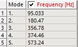
1) source is based on an article where they did theoretical/ ansys simulation for leaf spring. and the percentage of difference is less than 10% for first 3 natural frequency (fixed ends)
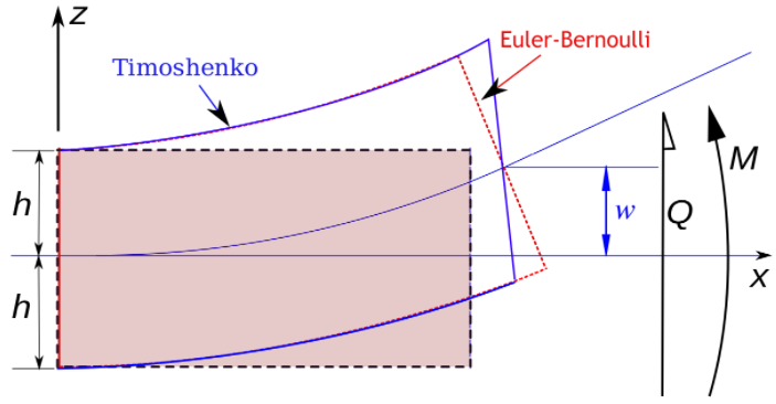
2) using Euler's equation to find the natural frequency
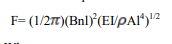
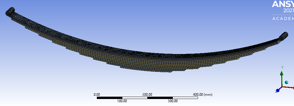
3) i have modeled the leaf spring using solidworks my leaf spring consists of 10 leaves so i modeled each leaf separately and then did assembly, then saved as .IGES
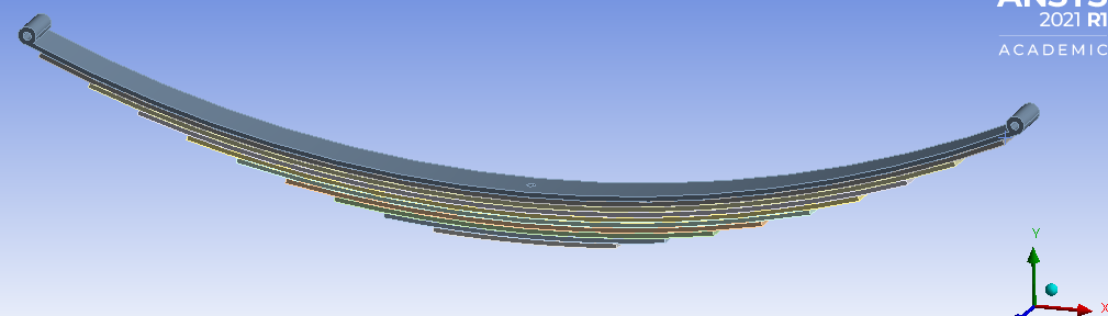
4) the connections are bonded between each leaf
5) solid elements
6) neither
7) i dont know how many elements
i am using ansys student version and i am not that advanced when it comes to meshing
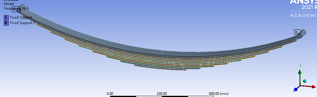
below is the formula used, model, meshing, results
based on theoretical calculation results of natural frequency is f1 = 90.9Hz, f2 = 250.4 Hz, f3 = 491 Hz


thank you
June 17, 2021 at 7:35 amErKo
Ansys EmployeeHI
I am not convinced that the theoretical calculation is comparable since it must have some simplifications (try to see what these are).
The comparisons and validations of the FEA results, should be done against experimental modal measurements on this structure.
All the best
Erik
June 17, 2021 at 10:01 amahmadsamih1
Subscribernoted Mr. Erik thank you
June 17, 2021 at 11:57 ampeteroznewman
SubscriberI agree with both points Erik made.
Comparing a theoretical equation result with an FEA result is useful, but you have to consider the fact that the equation contains simplifying assumptions. For example, an FEA solid model is computing shear deformation while an Euler-Bernoulli Beam equation ignores shear deformation. A physical beam in an experiment has shear deformation but for long slender beams in bending, the shear deformation is negligible.
The link below is to a project done by a student who compared the Euler beam vibration results to his own FEA code. I suggest you build an ANSYS model that matches one of the configurations in this paper to see if your Modal analysis gives results closer to the equations and results in this paper.
https://www.researchgate.net/publication/304123808_Determination_of_Natural_Frequency_of_Euler's_Beams_Using_Analytical_and_Finite_Element_Method
June 18, 2021 at 7:13 amRameez_ul_Haq
Subscriber, Euler-Bernoulli beam theory also has an assumption that the cross-sections along the beam always remain perpendicular to the neutral axis. But in reality, there are no cross-sections of any beam. So what is the importance of this assumption?
June 18, 2021 at 3:44 pmpeteroznewman
SubscriberCross sections perpendicular to the neutral axis can be physically drawn on the side of a straight beam with a pencil. The more modern approach would be to spray a pattern of dots on the side surface. When a short stubby beam has a load applied, it can be observed and measured that the lines that used to be perpendicular are no longer perpendicular due to the deformation of material in the beam.
In an FEA model with nice square hex elements, the nodes can be arrayed along the neutral axis and along lines perpendicular to that. When the deformed shape is plotted in a nonlinear analysis with large deflection on, it can be observed and measured that the lines that used to be perpendicular are no longer perpendicular.
https://structville.com/2017/07/solved-examples-on-shear-deformation-of-one-span-beams-using-virtual-work-method.html
Viewing 7 reply threads- The topic ‘Modal analysis natural frequency results percentage difference very high’ is closed to new replies.
Innovation SpaceTrending discussionsTop Contributors-
6284
-
1906
-
1457
-
1308
-
1022
Top Rated Tags© 2026 Copyright ANSYS, Inc. All rights reserved.
Ansys does not support the usage of unauthorized Ansys software. Please visit www.ansys.com to obtain an official distribution.
-