

-
-
May 31, 2021 at 2:58 pm
cqtavee
SubscriberHi All
I am trying to simulate this example recently: Edge coupler – Lumerical Support
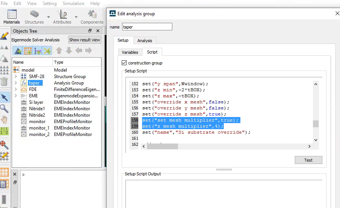
In the Script file of the no substrate case, (file name: Edge_Coupler_No_Substrate.lms) they are using codes to add taper structures. However, when they are adding the Si substrate override mesh, they used these two lines (line 158 and 159) of codes which cannot run on my computer.
set("set mesh multiplier",true);
set("z mesh multiplier",4);
May I ask what is the meaning of these two lines? Are they important for this program?
June 1, 2021 at 12:59 pmGuilin Sun
Ansys EmployeeHi, This is a special feature for MODE product: it means thatthe override mesh size changes the multiplier times from the original mesh .When the "mesh multiplier" is larger than 1,the mesh is finer; when it is smaller than 1, it is coarser.
set("set mesh multiplier",true); to enable this feature
set("z mesh multiplier",4); to assign value
I tested both R1.3 and R1.4 in FDE and both work. here is the test for the same file you mentioned:
 Please check the error message and make some modifications after some diagnoses.
You can enable anther feature (by default) to directly assign the override mesh:
The script is similar. Please try.
Or you may need to update the version. or please tell us what is your computer OS version.
June 1, 2021 at 1:30 pmSubscriberHi!
Thank you so much! I noticed a wired thing:
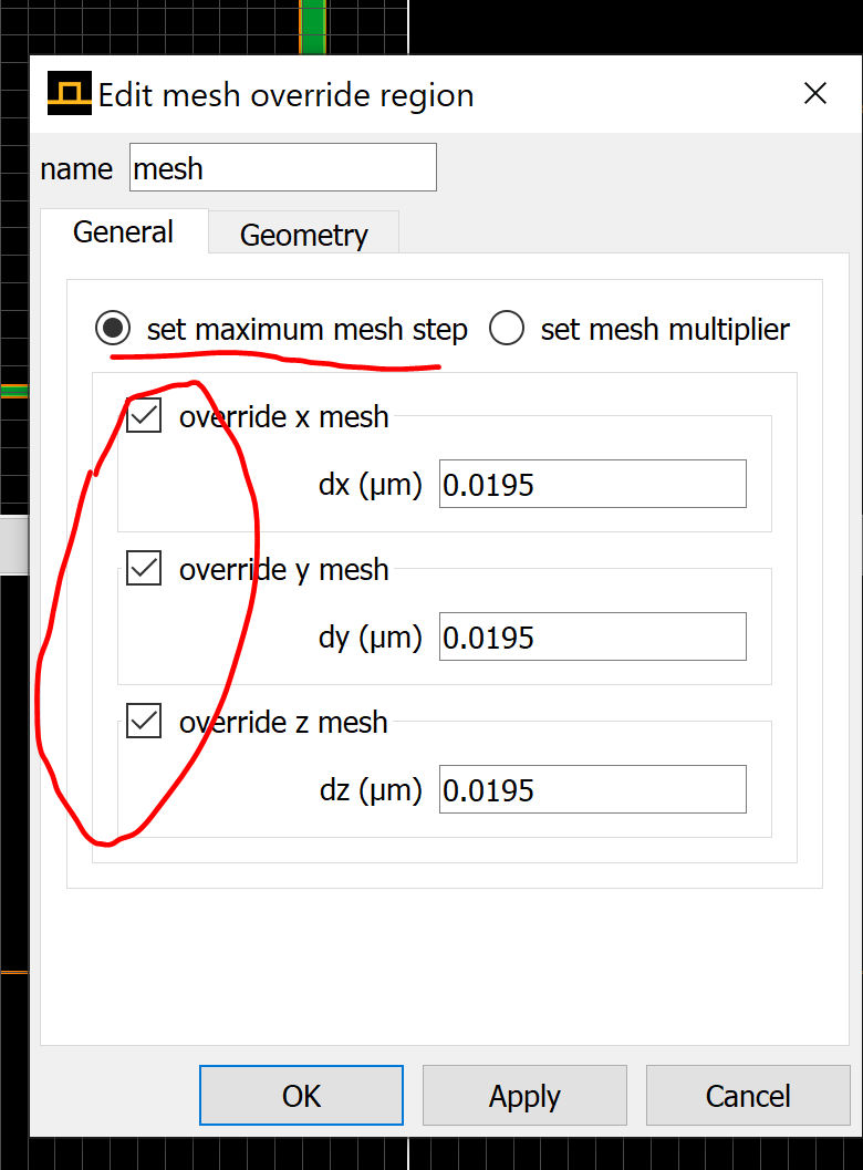
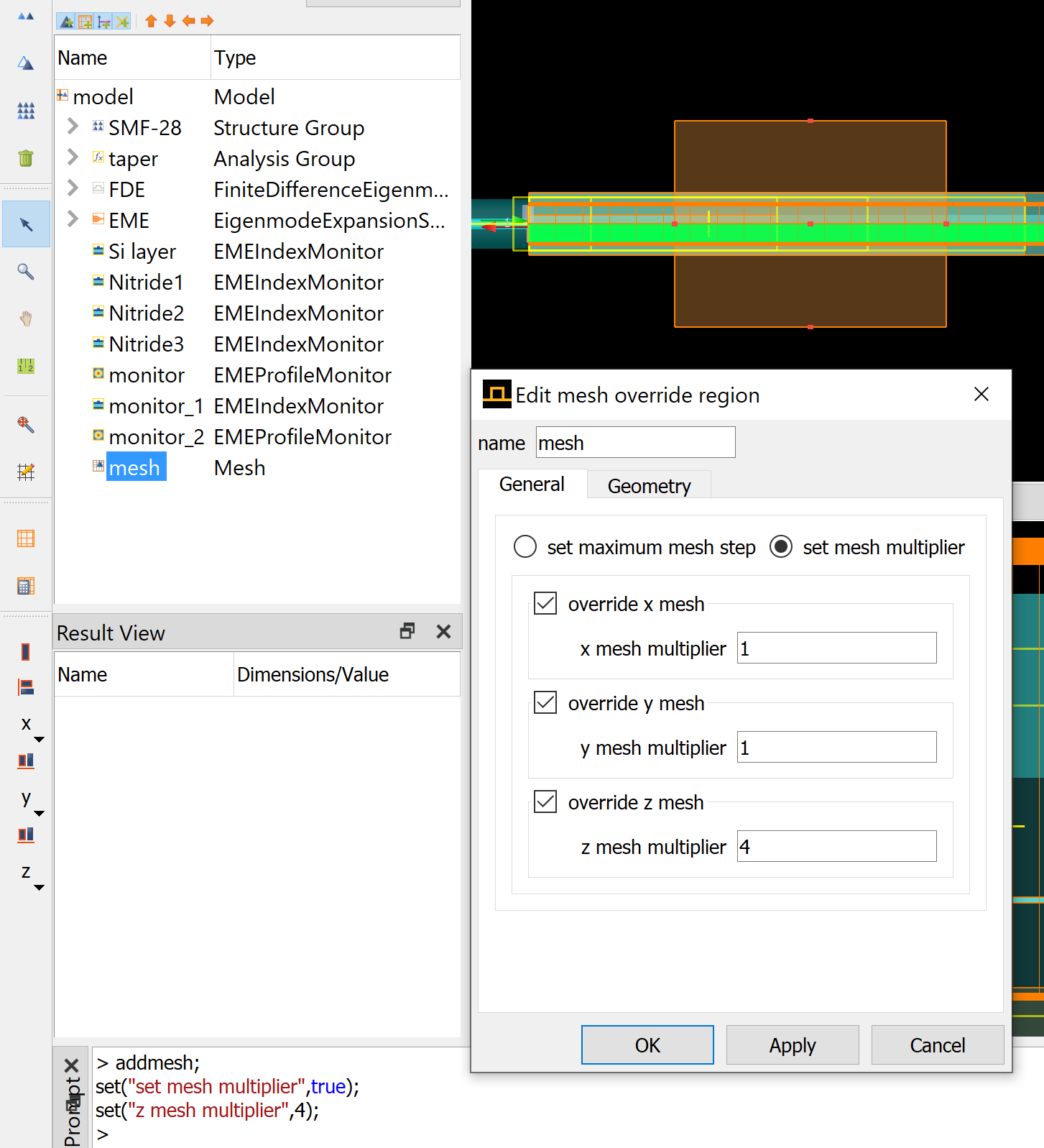
When I am running the script to add the mesh, the two checkboxes are called "set maximum mesh step" and "set equivalent index". That's where the error comes from. Because there is no checkbox called "set mesh multiplier".
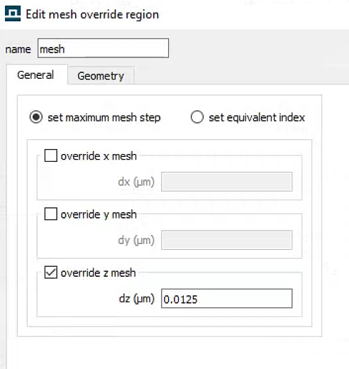
However, when I add the mesh manually, the two checkboxes are changed to "set maximum mesh step" and "set mesh multiplier" magically. And the window looks the same as the screenshot you showed.
(I'm using R2.3 version)
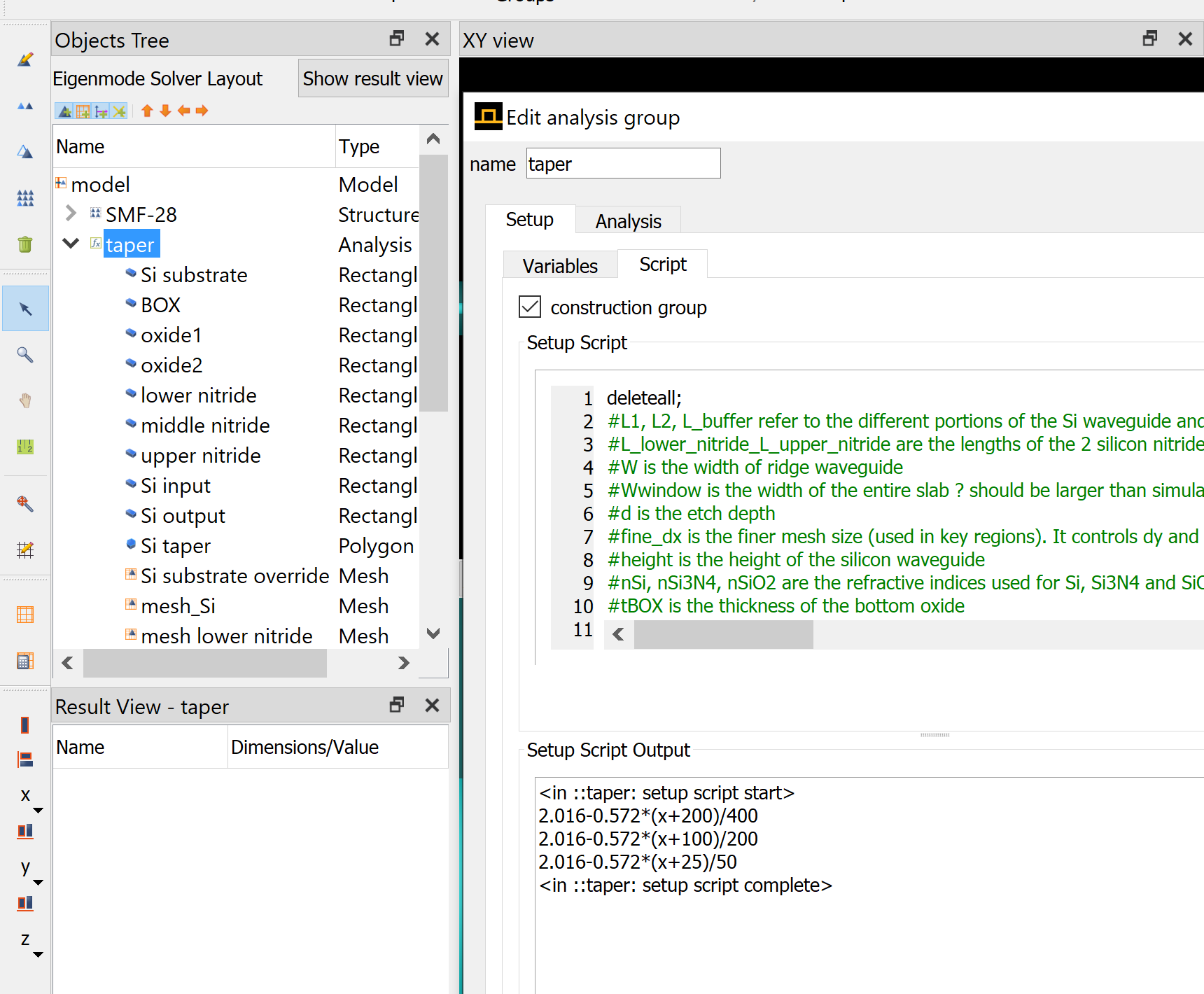
June 1, 2021 at 1:57 pmSubscriberI copied down the scripts and added the same SMF-28 fibre by codes. But I cannot get the same mode profile as the example project. I'm very sure I'm using the same parameters like the example. The first one is my result, and the second is the mode profile from the example file.
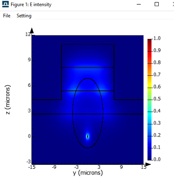
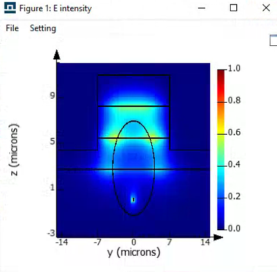 My codes are attached. I was thinking the problem is from the mesh setting. But now it looks like meshes are correct.
Very appreciate it if you could give some idea about finding where the problem comes from. I did not do much modification but just add fibre and fde simulation area.
June 1, 2021 at 2:36 pmAnsys EmployeeI am not sure what version and computer OS you are using. I tested it works fine:
Similarly for FDE.
I guess you are using varFDTD solver, which does not work.
As for the mode issue, please write a separate post.
November 3, 2023 at 11:07 pmNathan Lin
SubscriberHow do I script in the mesh order of a structure in a for loop? Let's say taper 1 to 64?
set("set mesh order, 2)?
how does it know become name specific for the mesh order setting?
Viewing 5 reply threads- The topic ‘About mesh multiplier in MODE’ is closed to new replies.
Innovation Space Trending discussions
 Top Contributors
-
peteroznewman
 4728
4728 -
scabo
 1565
1565 -
Dennis Chen
 1386
1386 -
javat33489
 1242
1242 -
Shyam Prasad V Atri
1021
Top Rated Tags
© 2026 Copyright ANSYS, Inc. All rights reserved.
Ansys does not support the usage of unauthorized Ansys software. Please visit www.ansys.com to obtain an official distribution.
-


The Ansys Learning Forum is a public forum. You are prohibited from providing (i) information that is confidential to You, your employer, or any third party, (ii) Personal Data or individually identifiable health information, (iii) any information that is U.S. Government Classified, Controlled Unclassified Information, International Traffic in Arms Regulators (ITAR) or Export Administration Regulators (EAR) controlled or otherwise have been determined by the United States Government or by a foreign government to require protection against unauthorized disclosure for reasons of national security, or (iv) topics or information restricted by the People's Republic of China data protection and privacy laws.


