

TAGGED: fluid-flow
-
-
May 7, 2021 at 1:16 pm
AmerM97
SubscriberHi,
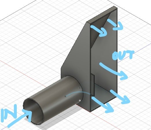
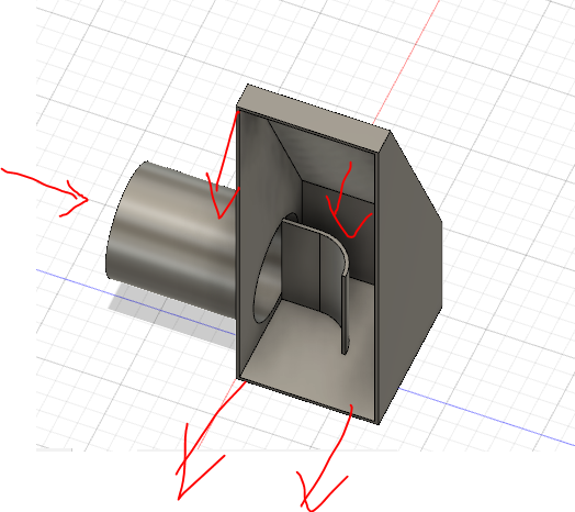
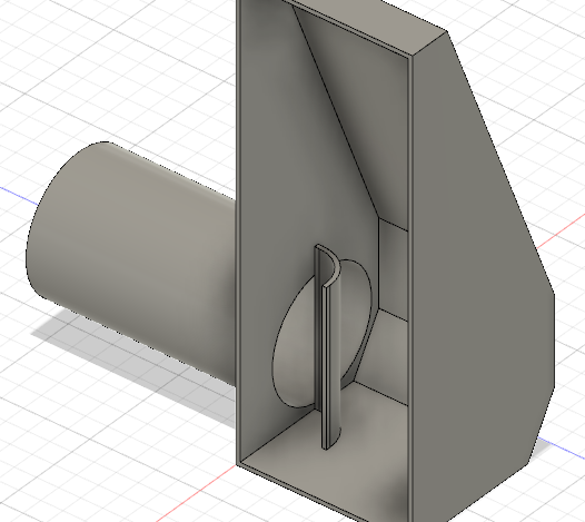
I'm trying to simulate an internal flow of intercooler end tanks. I want to design them as best as possible while keeping it simple because of welding.
I want to see how air travels from inlet ( the opening for a tube) towards the end cap.
This is my model.
May 7, 2021 at 1:32 pmRob
Forum ModeratorHave you done any of the tutorials? They may not be your exact model but do teach the basics and show you the various post processing functions that are available.
May 7, 2021 at 1:36 pmSubscriberAre the tutorial located under Courses?
-No I haven't, I've looked up some tutorials on youtube.
May 7, 2021 at 1:40 pmForum ModeratorClick on Help and you'll find tutorials for pretty much all the software you can use in Student.
May 7, 2021 at 8:42 pmSubscriberI have followed this tutorial : https://www.youtube.com/watch?v=f_pCqzYr39Y&t=348s , but for material I used air. All computations went fine, but when I reach results and Im on View 1-4 it doesnt matter it displays black screen why is this?
does my part need to be hollow or full ?
May 10, 2021 at 12:38 pmForum ModeratorIf all graphics screens are black (and nothing else shows up) it's graphics related: have a look in /forum/categories/ansys-free-student-software and /forum/categories/ansys-products as it's come up before.
May 10, 2021 at 2:32 pmSubscriberThank you, I have managed to make my first simulations, the program is lovely.
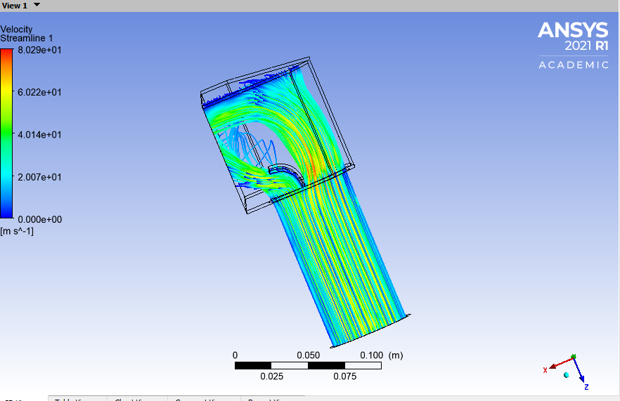
Do you maybe know why the stream-lines aren't projecting after my dispersion fin/ plate, like other lines ?
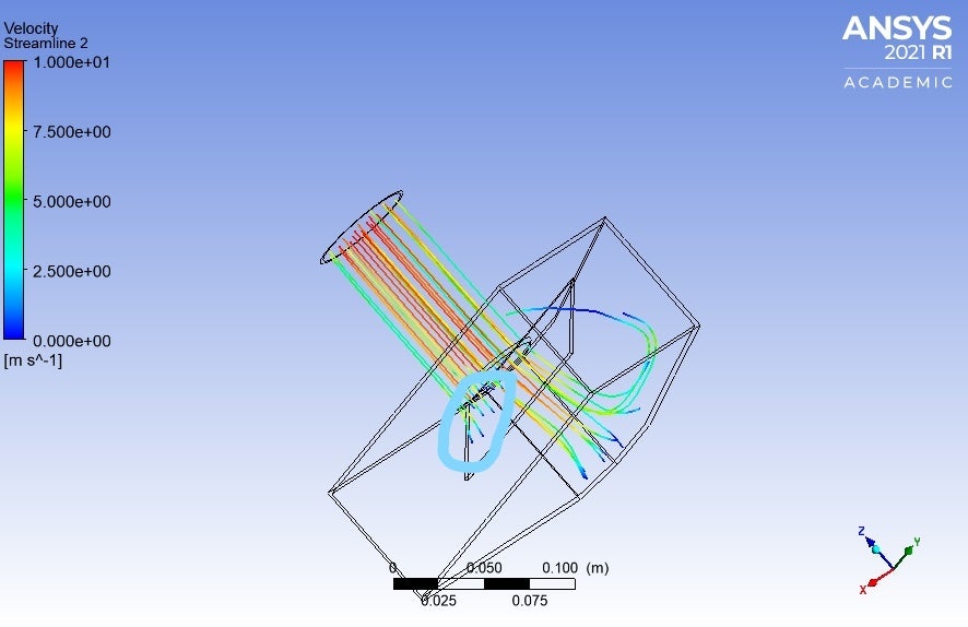 Is there a way to extend the stream lines to see how the "move"
May 10, 2021 at 2:56 pmForum ModeratorStreamlines shouldn't pass through the plate (assuming it's solid). Where's the outlet?
May 10, 2021 at 3:53 pmSubscriberWell they aren't passing thru it, but when they "hit it" they just stop.
 Shouldn't the streamlines that hit the curved plate follow the shape of the curve and deflect to the right, and not just stop. I can't figure this out, so I could configure shape of the fin the optimal flow efficiency. Because my most successful model has this.
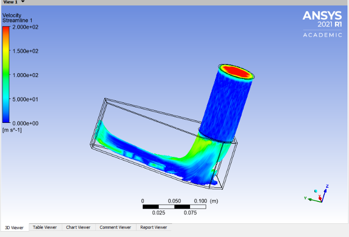
Has 1/2 of the tank un-used - no streamlines.
Does number of points = more realistic representation of air travelling ( represented via streamlines)
Thank you for your replies.
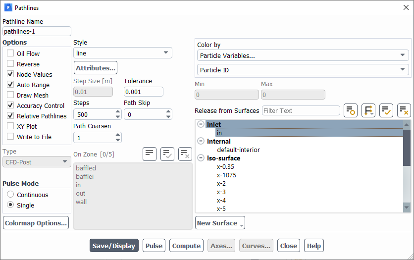
May 11, 2021 at 9:47 amForum ModeratorAre you using pathlines or massless particles? Also check the max steps in the pathline panel. Note, pathlines follow the flow, if you have dead zones you won't see many pathlines.
May 11, 2021 at 11:08 amSubscriberWell I'm almost leaving everything to default.
I import the model-> Do volume extract in Space claim
Mesh- Select create new named selections for inlet, outlet, and walls - Generate mesh
Setup- Models ( energy equation - ON), Boundary conditions - Inlet - Magnitude velocity ( I have played with numbers 1-200 m/s - i get similar results)
Run calculation- Number of iterations- 100 - Calculate
Results-Add Streamline- Start from: inlet ; # of points : 1000
I'm not sure where you select pathlines or massless particles?
All other settings I left to default
May 11, 2021 at 12:50 pmForum ModeratorPathlines are in the Results section, and there's a value for max steps: increase that. You'll likely need more than 100 iterations, and if the results are similar for 1-200m/s something is very wrong with your model!
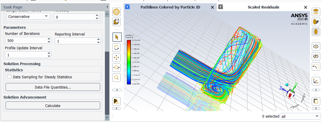
Not sure where you get 1000 points from, increase the number of steps, 2500 is probably enough but check for their fates in the TUI as all should be escape with few/none as incomplete.
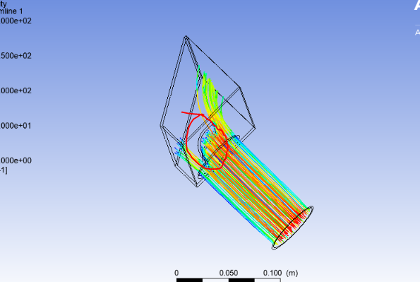
May 11, 2021 at 1:52 pmSubscriber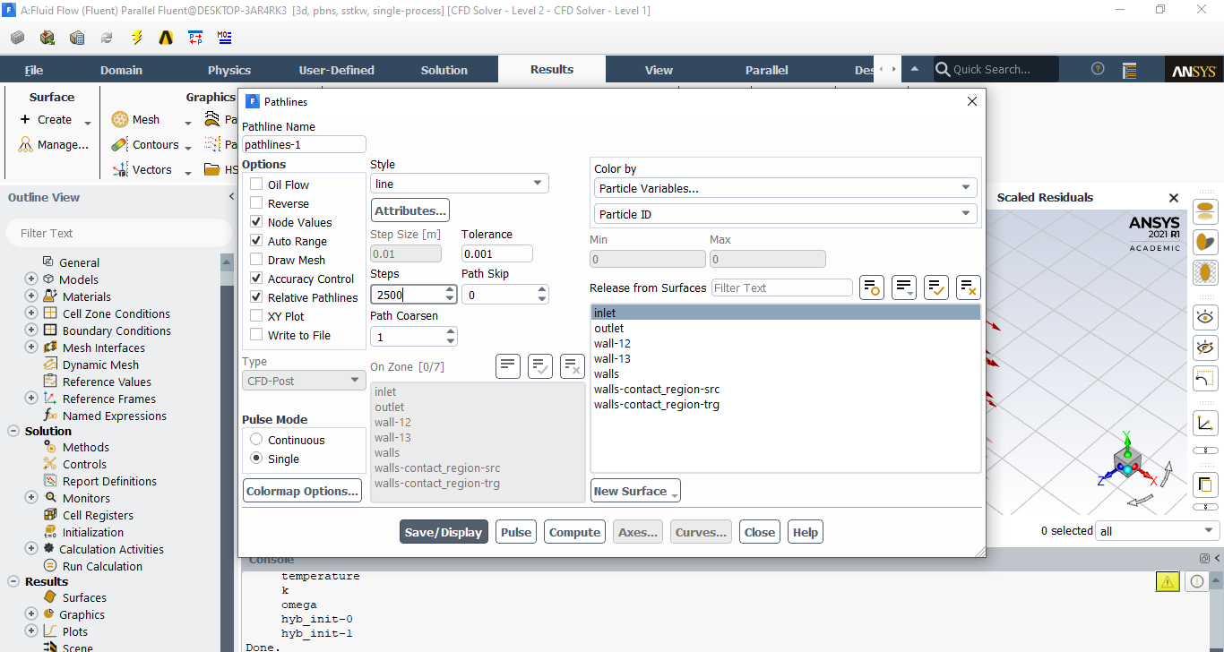
 iteration 500
monitors 1e-6
mesh 5mm and its not again again being deflected by the fin
 When I generate the faces for "walls" i click select all, hold CTRL and click on Inlet and outlet(to deselect them) to generate "walls" boundary
May 11, 2021 at 3:38 pmForum ModeratorWhy have you got a non-conformal interface in the model? Delete the contact region in Meshing as I think the tolerance has picked up the baffle: you may be able to delete the non-conformal in Fluent then set the interface surfaces to wall. The clue is in the surface labels in the first image of your last post.
May 11, 2021 at 4:29 pmSubscriberThank you now it's working after I deleted one of the wall boundary conditions, and change the way I create inlet and outlet. Very powerful software and easy to use, amazing.
I really appreciate the time you took to read, and reply to me. This is going to be so much helpful, thank you!
Thank you ANSYS for making this available !
May 12, 2021 at 3:49 pmForum ModeratorYou're welcome, glad to hear it's working. The automatic interface tool is very useful at times, but less useful with baffles and aerofoils as it can pick up the two faces due to the tolerancing.
As an aside, we usually model baffles as a thin wall as it negates the need to resolve the thin faces surrounding them.
Viewing 15 reply threads- The topic ‘Internal fluid flow setup’ is closed to new replies.
Innovation Space Trending discussions
 Top Contributors
-
peteroznewman
 6279
6279 -
scabo
 1906
1906 -
Dennis Chen
 1457
1457 -
javat33489
 1308
1308 -
Shyam Prasad V Atri
1022
Top Rated Tags
© 2026 Copyright ANSYS, Inc. All rights reserved.
Ansys does not support the usage of unauthorized Ansys software. Please visit www.ansys.com to obtain an official distribution.
-


The Ansys Learning Forum is a public forum. You are prohibited from providing (i) information that is confidential to You, your employer, or any third party, (ii) Personal Data or individually identifiable health information, (iii) any information that is U.S. Government Classified, Controlled Unclassified Information, International Traffic in Arms Regulators (ITAR) or Export Administration Regulators (EAR) controlled or otherwise have been determined by the United States Government or by a foreign government to require protection against unauthorized disclosure for reasons of national security, or (iv) topics or information restricted by the People's Republic of China data protection and privacy laws.
