STEP 4: DC Motor controlled with buttons — Lesson 6
We take the circuit and the model from before and we add devices.
The Arduino circuit
For this step, we need 3 buttons, 1 DC Motor, and 1 Bridge.
The objective is to start the motor with the right button and modify its speed with an up and down button.
Plugs:
- Right button on D3
- Up button on D4
- Down button on D5
- DC Motor on D2
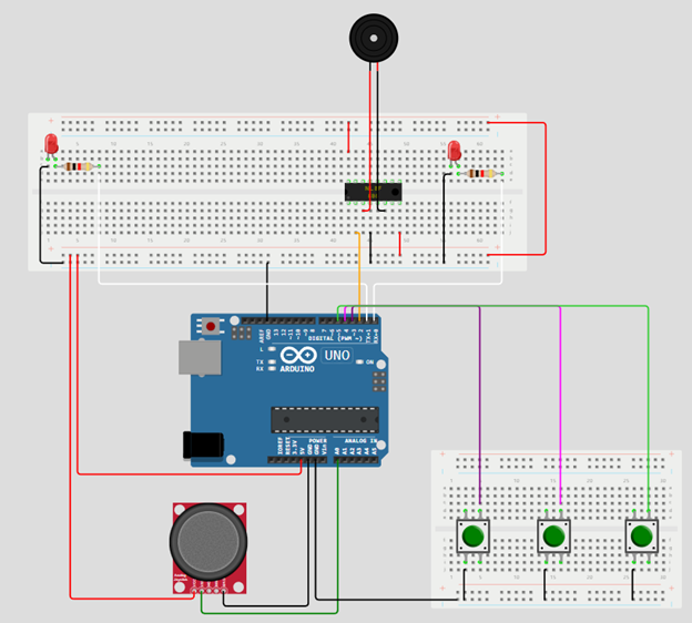
Image 17
The Ansys SCADE application model
Copy the PlanePackageStep1 in the project to have a PlanePackageStep2. We will update this package.
Design the Architecture operator, SystemPlane:
In this section, we will implement the following Ansys SCADE application operator:
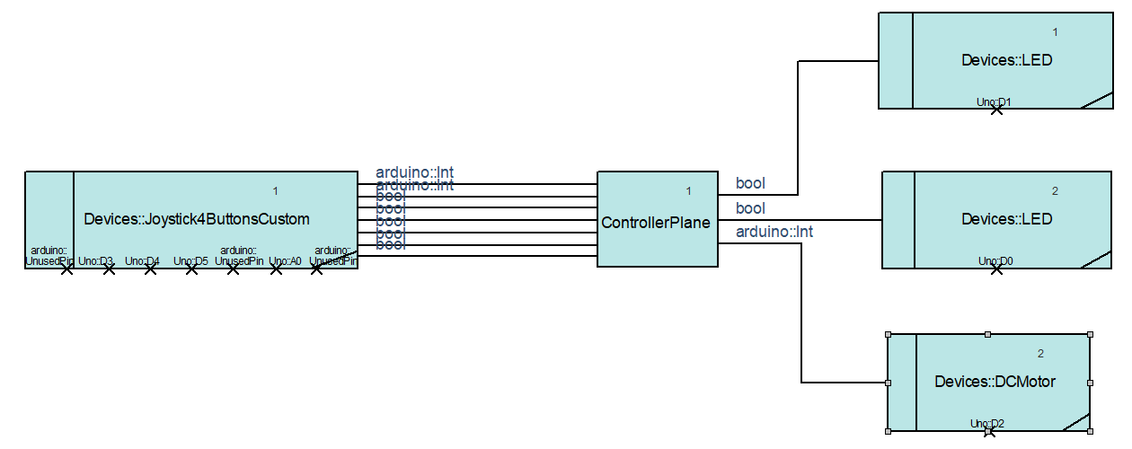
Image 18
- Modify in the new package the Joystick4ButtonsCustom pins.
- Joystick4ButtonsCustom pins:
- Sel = arduino::UnusedPin
- RB = Uno::D3
- UB = Uno::D4
- DB = Uno::D5
- LB = arduino::UnusedPin
- Xpos = Uno::A0
- Ypos = arduino::UnusedPin
- Joystick4ButtonsCustom pins:
- Drag and drop in the model of the Device DC Motor for the Arduino library.
- DC Motor pin:
- speed_pin = Uno::D2
- DC Motor pin:
- Plug the new device DC Motor to the ControllerPlane operator when you have done the ControllerPlane part.
Design the Controller operator, ControllerPlane:
In this section, we will implement the following state machine:
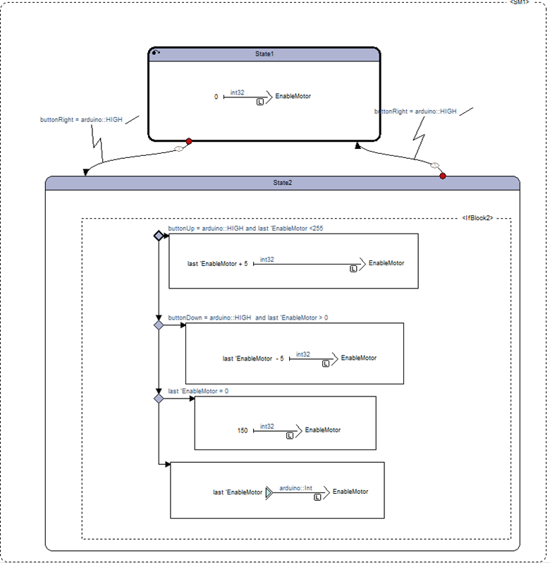
Image 19
- Add an output named EnableMotor with arduino::Int
- Add the state machine to control the DC Motor.
- When the right button is pressed the DC Motor starts. If it is pressed again the DC Motor stops.
- If the DC Motor is started
- Up button increases the speed.
- Down button decreases the speed.
- In order to do that you have to use “Last” for EnableMotor output.
Generate the code
- In settings, select the root operator in General and the Architecture in the Arduino Wrapper.
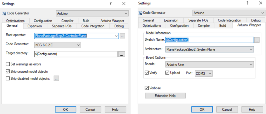
Image 20
- Now that your project is configured for the Arduino wrapper generation, you can click on the “Generate” button to generate the code and upload it on the board.
![]()
Now everything should work as expected. We control our LEDs with the xJoystick and we’ve added the control of the DC Motor with 3 buttons.
You are being redirected to our marketplace website to provide you an optimal buying experience. Please refer to our FAQ page for more details. Click the button below to proceed further.