STEP 2: LEDs controlled with joystick — Lesson 4
Now that the project has been created, we'll start by building our plane controller in Arduino. As we said earlier, the goal here is to have a small plane model made in the Ansys SCADE application and run on Arduino. So, to achieve this, we'll start by building the Arduino circuit and then making the associated Ansys SCADE application model.
The Arduino circuit
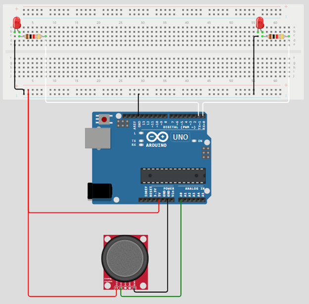
For this step, we need a joystick and 2 LEDs.
The objective is to control the LEDs with the joystick. If we go to the left, we want the left LED to be on.
Plugs:
- Plug the x joystick into A0.
- Plug the right LED to D0.
- Plug the left LED to D1.
- Plug the power and the ground.

Image 6
The Ansys SCADE software model
Now we are developing the SCADE model by following these steps:
- Design the Ansys SCADE application package that will contain the Ansys SCADE application model
- Design an Architecture operator to specify which devices we are using.
- Design a Controller operator to define the behavior of our model.
- Simulate the Controller operator to be sure that the behavior is the expected one.
- To finish, we’ll generate the code and try it on our Arduino.

