STEP 3: Design the Ansys SCADE application package — Lesson 5
- Create a Package named “PlanePackageStep1”.
- Add two operators, one ControllerPlane and one SystemPlane.
- Add two constants.

Image 7
Design the architecture operator, SystemPlane:
In this section, we will implement the following Ansys SCADE software operator:

Image 8
- Open SystemPlane operator
- Drag and drop in the model 1 Joystick4ButtonsCustom and 2 LEDs from the Devices package in the Arduino library.
- Add the pins to the device by clicking on the operator and opening the parameters tab in the properties.
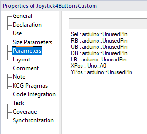
Image 9
-
- Joystick4ButtonsCustom pin:
- Sel = arduino::UnusedPin
- RB = arduino::UnusedPin
- UB = arduino::UnusedPin
- DB = arduino::UnusedPin
- LB = arduino::UnusedPin
- Xpos = Uno::A0
- Ypos = arduino::UnusedPin
- Left LED pin:
- Uno: D1
- Right LED pin:
- Uno: D0
- Joystick4ButtonsCustom pin:
- In the middle of the model, drag and drop the ControllerPlane operator.
- Now do the ControllerPlane part and then go back into your SystemPlane operator to plug all the devices together. The Joystick4ButtonsCustom with the ControllerPlane and the ControllerPlane with the LEDs. Make sure that you plug the right output to the right input.
Design the controller operator, ControllerPlane:
In this section we will implement the following “If block”:
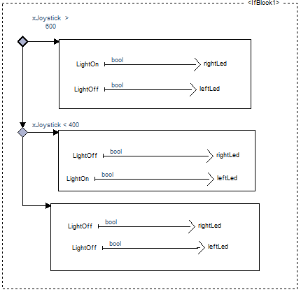
Image 10
- Open ControllerPlane operator
- Add the inputs xJoystick, yJoystick, selButton, rightButton, upButton, leftButton, downButton.
- Types:
- xJoystick – yJoystick → arduino::Int
- buttons → bool
- Types:
- Add the outputs leftLed and rightLed.
- Types:
- LEDs → bool
- Types:
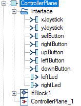
Image 11
- Create a step machine to control the 2 LEDs with the joystick.
- When xJoystick > 600 the right LED lights up and the left one lights down.
- When xJoystick < 400 the left LED lights up and the right one lights down.
- If the joystick is neutral, none of the LEDs start.
![]()
Now, you have to return to the architecture operator “SystemPlane” and plug the devices into the controller. Once you have done that you can check your architecture to be sure that there are no errors.
Simulate the controller
- You can simulate your controller directly in the Ansys SCADE application. In order to do that you have to choose “Simulation” in your setting list.

Image 12
- Once you have selected “Simulation” you can open the settings and select the right operator to simulate which is ControllerPlane from the package PlanePackageStep1.
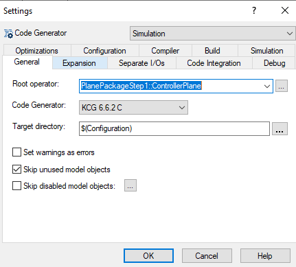
Image 13
- Now you can start the simulation by clicking on the “Run” button.
![]()
- You should have now this window:
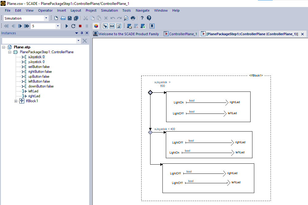
Image 14
- From here you can change the value of the xJoystick and see if your controller is working as intended. If the xJoystick is >600 the RightLed should light up, if the xJoystick is <400 the LeftLed should light up. And if the xJoystick is between 400 and 600, none of the LEDs should be on.
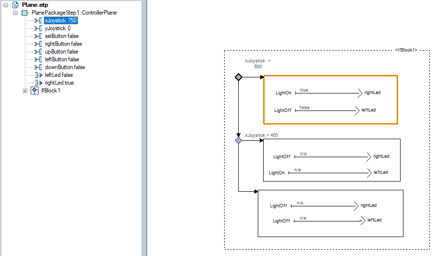
Image 15
Generate the code
Now we will generate and upload the code into the Arduino board.
- Open the settings.
- First you must select the Root operator in General. This is where you select the controller to know what behavior to generate.
- Second you must select the Architecture in the Arduino Wrapper. This is where you specify each device you are using and what pins they’ll have.
- You have to click on “Ok” once you have selected the operators if you want to save the settings.
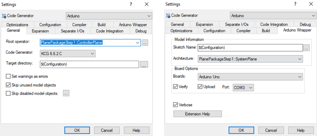
Image 16
Note: Don’t forget to tick Upload and select the right port if you want to upload the sketch on the platform.
- Now that your project is configured for the Arduino wrapper generation, you can click on the “Generate” button to generate the code and upload it on the board.
![]()
Everything should work as expected on your Arduino. If you move the xJoystick to the left the left LED lights up. The same for the right LED if the xJoystick is to the right.

