-
-
April 8, 2025 at 12:31 pm
Watch & Learn
ParticipantDiscovery provides intuitive tools that are ideal for reverse engineering. With Discovery, STL files and solid models can be effortlessly modified to recreate accurate models for parts and fixtures.
In this tutorial series, we’ll be working with faceted geometries. In the first three videos, you’ll learn how to create boundary patches using skin surface tool. The first video covers how to create boundary patches using control points and vertices. The second and third videos will demonstrate how to create periodic boundary patches—first by selecting points along the periphery and then using multiple planes. In the final tutorial, we’ll explore various selection options available for STL files. Let’s get started!
Note: These video tutorials have Chinese (simplified), Japanese and English subtitles embedded in them, please activate them by navigating to the gear icon (âš™) and choose the language from captions.
- Creating Boundary Patches from STL in Discovery: In this video tutorial, we will see how to use the Skin Surface tool in Discovery to create boundary patches on faceted geometries. You’ll learn how to define boundaries using control points and vertices, adjust fit using sampling and tolerance, and explore different boundary creation methods. This is ideal for handling complex, organic STL surfaces in reverse engineering workflows.
Â
- Creating Periodic Blended Patches from STL in Ansys Discovery Part 1: In the first part of this video, we will see how to create periodic or blended surfaces using the Skin Surface tool in Discovery. You’ll learn how to define circular boundary profiles by selecting points around the model and generate smooth surface patches between them. This method is ideal for handling complex organic cylindrical shapes in reverse engineering.
- Creating Periodic Blended Patches from STL in Ansys Discovery Part 2: In the second video, we will see how to create periodic surfaces using multiple planes in Discovery. Instead of manually sketching, we’ll automate boundary creation by slicing the geometry with planes and generating blended surface patches. This method helps achieve cleaner and more controlled surfaces, especially for long or complex scans.
- STL Selection options in Ansys Discovery: In the last video of this series, we will see how to work with STL facet selection in Discovery, exploring various methods to select, move, and organize mesh geometry efficiently—ideal for reverse engineering workflows and precise editing.
-

Introducing Ansys Electronics Desktop on Ansys Cloud
The Watch & Learn video article provides an overview of cloud computing from Electronics Desktop and details the product licenses and subscriptions to ANSYS Cloud Service that are...

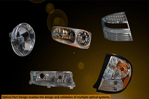
How to Create a Reflector for a Center High-Mounted Stop Lamp (CHMSL)
This video article demonstrates how to create a reflector for a center high-mounted stop lamp. Optical Part design in Ansys SPEOS enables the design and validation of multiple...

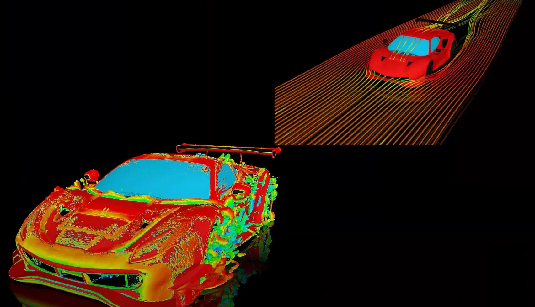
Introducing the GEKO Turbulence Model in Ansys Fluent
The GEKO (GEneralized K-Omega) turbulence model offers a flexible, robust, general-purpose approach to RANS turbulence modeling. Introducing 2 videos: Part 1Â provides background information on the model and a...

Postprocessing on Ansys EnSight
This video demonstrates exporting data from Fluent in EnSight Case Gold format, and it reviews the basic postprocessing capabilities of EnSight.
- Surface to solid creation in SpaceClaim
- FAQ – Share Topology is now available in Discovery 2021 R2
- Changing the visibility of bodies from transparent to opaque or vice-versa
- Ansys Discovery – Working with Components
- Discovery Quick Tip- How to update your geometry from a source CAD File
- Quick Tips for Volume extraction in SpaceClaim
- Split Face in SpaceClaim
- Ansys Discovery: Automatic External Volume Enclosure
- Selecting all inner faces of a body
- Stitch Faces & Split Edges Tools in SpaceClaim
© 2025 Copyright ANSYS, Inc. All rights reserved.