Blog Posts infinite loop
Array
(
[topic_list] => Array
(
[status] => 1
[topics] => Array
(
[1] => Array
(
[topic_id] => 432393
[topic_title] => Unable to build the model entirely after parameterisation
[topic_content] => <p>Parameterized variables that were initially with a fixed value and now the same code doesn't work. </p><p>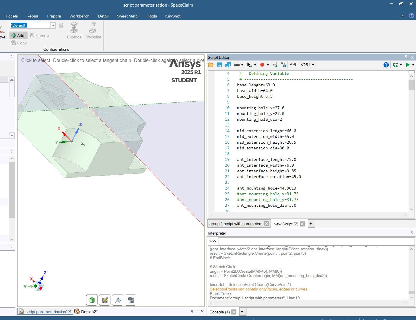 - Initial Code with values</p><p>
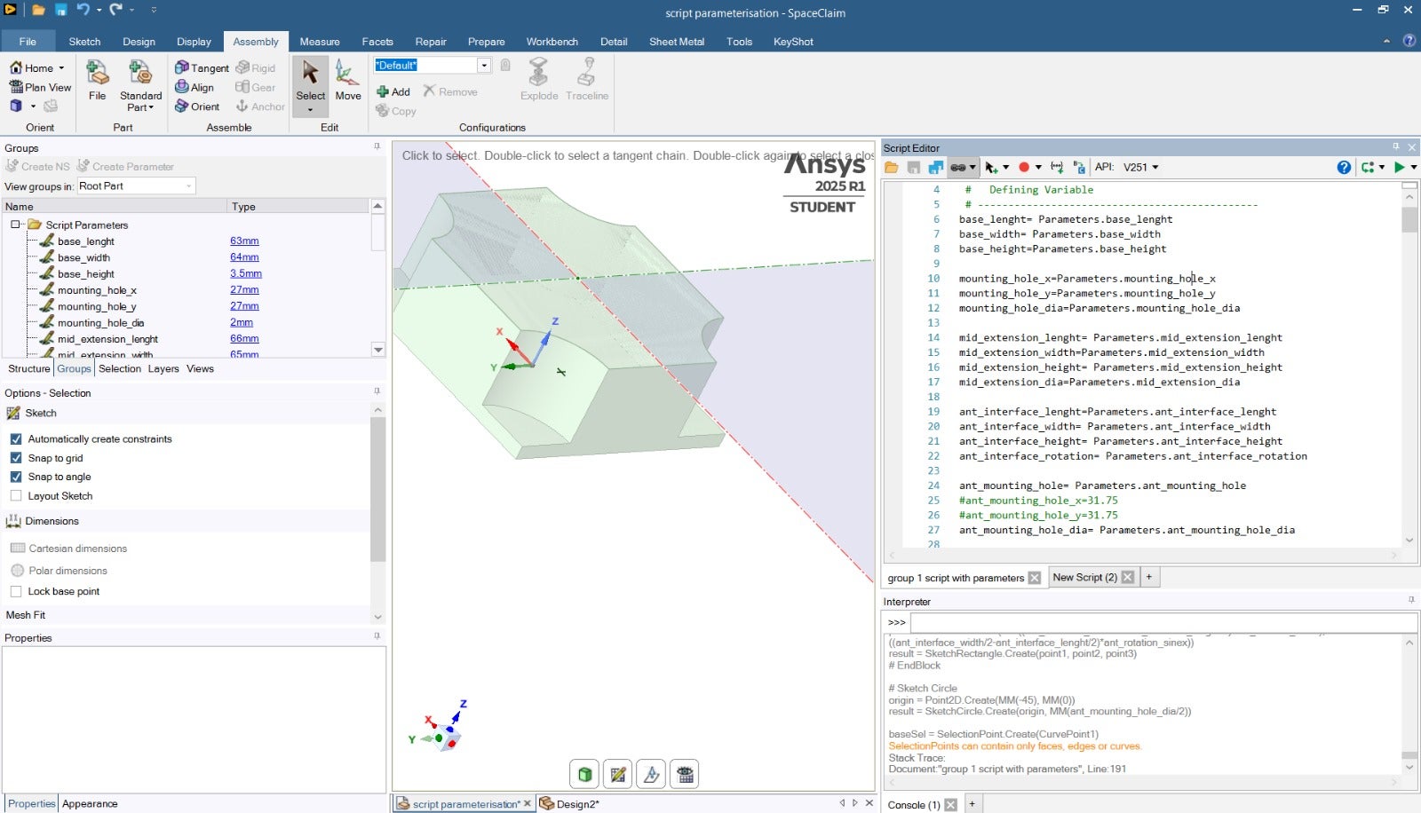 - Converted the variables to parameters and now the code stops working at the line shown in red in the picture below.
 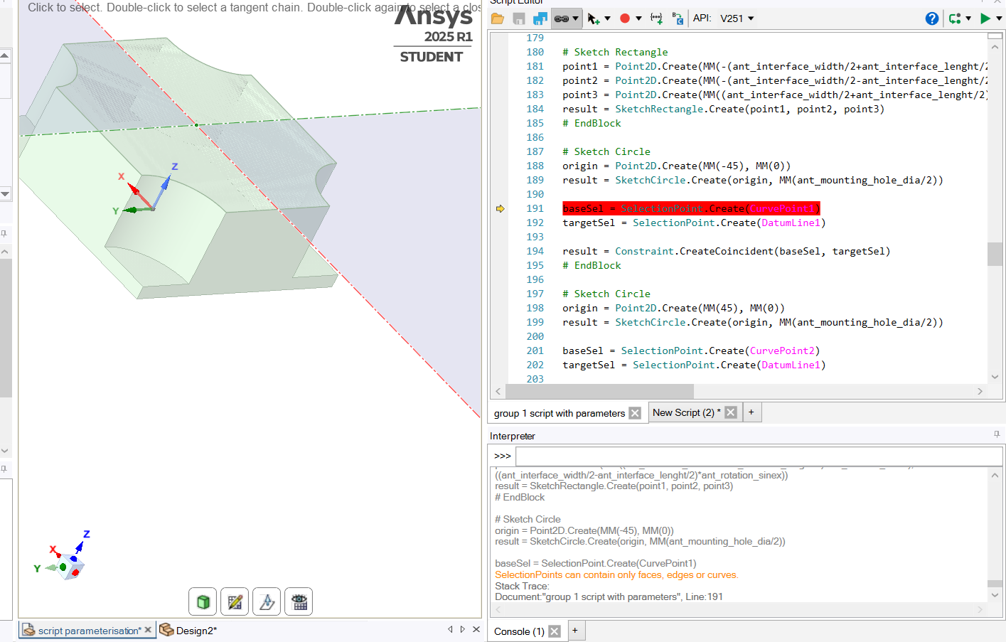 </p><p> </p><p> </p><p>Any ideas why this problem exists and how to solve? Thank you.</p>
[topic_link] => https://innovationspace.ansys.com/forum/forums/topic/unable-to-build-the-model-entirely-after-parameterisation/
[topic_status] => publish
[topic_published_date] => May 23, 2025
[author] => e1306841@u.nus.edu
[like_count] => 0
[reply_count] => 0
[view_count] => 2
)
[2] => Array
(
[topic_id] => 432158
[topic_title] => I missed 1 of 5 Structural Analysis classes. Is there any way to complete the se
[topic_content] => <p>I missed 1 of 5 Structural Analysis classes. Is there any way to complete the session?</p>
[topic_link] => https://innovationspace.ansys.com/forum/forums/topic/i-missed-1-of-5-structural-analysis-classes-is-there-any-way-to-complete-the-se/
[topic_status] => publish
[topic_published_date] => May 21, 2025
[author] => Young.hwangbo@honeywell.com
[like_count] => 0
[reply_count] => 1
[view_count] => 27
)
[3] => Array
(
[topic_id] => 431277
[topic_title] => ANSYS Forte port fuel injection, adding a second fuel at the inlet of piston com
[topic_content] => <p>I was looking at ANSYS Forte tutorial which uses Gasoline_1comp_49sp.cks as a fuel with the following breakdown; o2=0.1967</p><p> </p><p>h2o=0.0089</p><p> </p><p>co2=0.0192</p><p> </p><p>ic8h18=0.0562</p><p> </p><p>n2=0.7190.</p><p> </p><p>The question is how do I add another fuel to ic8h18?:Do I just change the ic8h18 fraction and add another fuel by clicking the pencil icon?</p><p> </p><p> </p><p>Tutorial link: https://ansyshelp.ansys.com/public/account/secured?returnurl=/////Views/Secured/corp/v242/en/forte_tut/i32376.html</p>
[topic_link] => https://innovationspace.ansys.com/forum/forums/topic/ansys-forte-port-fuel-injection-adding-a-second-fuel-at-the-inlet-of-piston-com/
[topic_status] => publish
[topic_published_date] => May 11, 2025
[author] => Hasan
[like_count] => 0
[reply_count] => 0
[view_count] => 107
)
[4] => Array
(
[topic_id] => 431190
[topic_title] => Why i am not able to change the Symmetric Axis
[topic_content] => <p>For some reason i am not able to change the symmetry axis for my 2D axisymmetric analysis. The system is rotating my model at Y axis instead of X axis... i have been trying to change it in the symmetry option but it is not taking it. see the attached pics..
</p><p> </p><p> </p><p>Any ideas why this problem exists and how to solve? Thank you.</p>
[topic_link] => https://innovationspace.ansys.com/forum/forums/topic/unable-to-build-the-model-entirely-after-parameterisation/
[topic_status] => publish
[topic_published_date] => May 23, 2025
[author] => e1306841@u.nus.edu
[like_count] => 0
[reply_count] => 0
[view_count] => 2
)
[2] => Array
(
[topic_id] => 432158
[topic_title] => I missed 1 of 5 Structural Analysis classes. Is there any way to complete the se
[topic_content] => <p>I missed 1 of 5 Structural Analysis classes. Is there any way to complete the session?</p>
[topic_link] => https://innovationspace.ansys.com/forum/forums/topic/i-missed-1-of-5-structural-analysis-classes-is-there-any-way-to-complete-the-se/
[topic_status] => publish
[topic_published_date] => May 21, 2025
[author] => Young.hwangbo@honeywell.com
[like_count] => 0
[reply_count] => 1
[view_count] => 27
)
[3] => Array
(
[topic_id] => 431277
[topic_title] => ANSYS Forte port fuel injection, adding a second fuel at the inlet of piston com
[topic_content] => <p>I was looking at ANSYS Forte tutorial which uses Gasoline_1comp_49sp.cks as a fuel with the following breakdown; o2=0.1967</p><p> </p><p>h2o=0.0089</p><p> </p><p>co2=0.0192</p><p> </p><p>ic8h18=0.0562</p><p> </p><p>n2=0.7190.</p><p> </p><p>The question is how do I add another fuel to ic8h18?:Do I just change the ic8h18 fraction and add another fuel by clicking the pencil icon?</p><p> </p><p> </p><p>Tutorial link: https://ansyshelp.ansys.com/public/account/secured?returnurl=/////Views/Secured/corp/v242/en/forte_tut/i32376.html</p>
[topic_link] => https://innovationspace.ansys.com/forum/forums/topic/ansys-forte-port-fuel-injection-adding-a-second-fuel-at-the-inlet-of-piston-com/
[topic_status] => publish
[topic_published_date] => May 11, 2025
[author] => Hasan
[like_count] => 0
[reply_count] => 0
[view_count] => 107
)
[4] => Array
(
[topic_id] => 431190
[topic_title] => Why i am not able to change the Symmetric Axis
[topic_content] => <p>For some reason i am not able to change the symmetry axis for my 2D axisymmetric analysis. The system is rotating my model at Y axis instead of X axis... i have been trying to change it in the symmetry option but it is not taking it. see the attached pics..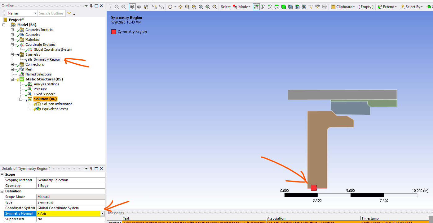 </p>
[topic_link] => https://innovationspace.ansys.com/forum/forums/topic/why-i-am-not-able-to-change-the-symmetric-axis/
[topic_status] => publish
[topic_published_date] => May 9, 2025
[author] => rajesh.parameshwariah@halliburton.com
[like_count] => 0
[reply_count] => 1
[view_count] => 65
)
[5] => Array
(
[topic_id] => 431156
[topic_title] => Discovery as external CAD option in Workbench, similar to Spaceclaim
[topic_content] => <p>Hi,</p><p>Is it possible to make the option to use as an external CAD also available to Discovery?</p><p>See screenshot below.</p><p>The reason is that now for Discovery CAD files, Mechanical makes a local copy of the CAD file, renames it to some generic SYS-... filename and points to that local copy. The link to the original CAD file is broken.<br>That is unwanted behavior. In case of Spaceclaim and the option "use a sexternal CAD" it keeps referencing to the original CAD file without making a local copy.</p><p>Ot is there another way to keep linking to the original CAD file instead of that Mechanical makes a local copy and renames it to SYS-something?</p><p>Thanks in advance!</p><p>
</p>
[topic_link] => https://innovationspace.ansys.com/forum/forums/topic/why-i-am-not-able-to-change-the-symmetric-axis/
[topic_status] => publish
[topic_published_date] => May 9, 2025
[author] => rajesh.parameshwariah@halliburton.com
[like_count] => 0
[reply_count] => 1
[view_count] => 65
)
[5] => Array
(
[topic_id] => 431156
[topic_title] => Discovery as external CAD option in Workbench, similar to Spaceclaim
[topic_content] => <p>Hi,</p><p>Is it possible to make the option to use as an external CAD also available to Discovery?</p><p>See screenshot below.</p><p>The reason is that now for Discovery CAD files, Mechanical makes a local copy of the CAD file, renames it to some generic SYS-... filename and points to that local copy. The link to the original CAD file is broken.<br>That is unwanted behavior. In case of Spaceclaim and the option "use a sexternal CAD" it keeps referencing to the original CAD file without making a local copy.</p><p>Ot is there another way to keep linking to the original CAD file instead of that Mechanical makes a local copy and renames it to SYS-something?</p><p>Thanks in advance!</p><p>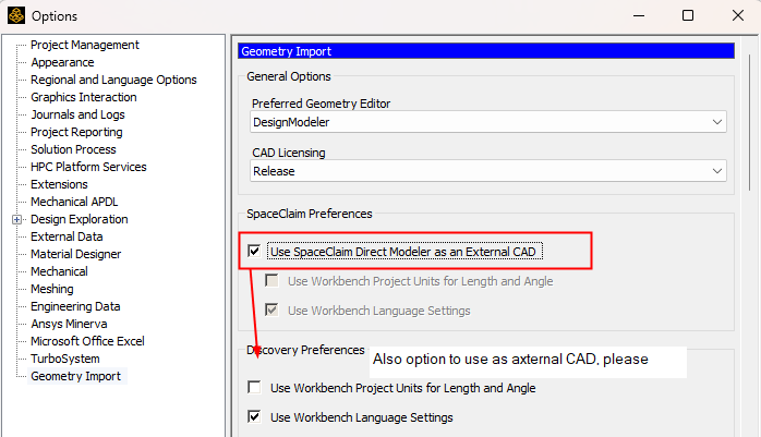 </p>
[topic_link] => https://innovationspace.ansys.com/forum/forums/topic/discovery-as-external-cad-option-in-workbench-similar-to-spaceclaim/
[topic_status] => publish
[topic_published_date] => May 9, 2025
[author] => SDB Engineering
[like_count] => 0
[reply_count] => 1
[view_count] => 49
)
[6] => Array
(
[topic_id] => 430929
[topic_title] => Ansys Discovery – Enclosure Tool, Freezes/lags when certain tasks are performed
[topic_content] => <p><p><p><p><p><p><p><p>UPDATED, I've partially figured out something is wrong with my Full Car model. But I haven't figured out a solution to fix my model. SEE BELOW<p><p><p><p><p>Dear Ansys team and fellow users,</p><p>On certain functions, in this case using the Enclosure tool. I need to make an enclosure for CFD simulation. Using Solidworks 2024 Assembly document (.SLDASM) However, after inserting the enclosure dismensions in and clicking on the green arrow, the loading circle mouse icon appears, and it doesn't seem to be able to 'unfreeze' itself. Tried 3 times, without any success. Had to force close Discovery via Task Manager.p><p>
</p>
[topic_link] => https://innovationspace.ansys.com/forum/forums/topic/discovery-as-external-cad-option-in-workbench-similar-to-spaceclaim/
[topic_status] => publish
[topic_published_date] => May 9, 2025
[author] => SDB Engineering
[like_count] => 0
[reply_count] => 1
[view_count] => 49
)
[6] => Array
(
[topic_id] => 430929
[topic_title] => Ansys Discovery – Enclosure Tool, Freezes/lags when certain tasks are performed
[topic_content] => <p><p><p><p><p><p><p><p>UPDATED, I've partially figured out something is wrong with my Full Car model. But I haven't figured out a solution to fix my model. SEE BELOW<p><p><p><p><p>Dear Ansys team and fellow users,</p><p>On certain functions, in this case using the Enclosure tool. I need to make an enclosure for CFD simulation. Using Solidworks 2024 Assembly document (.SLDASM) However, after inserting the enclosure dismensions in and clicking on the green arrow, the loading circle mouse icon appears, and it doesn't seem to be able to 'unfreeze' itself. Tried 3 times, without any success. Had to force close Discovery via Task Manager.p><p>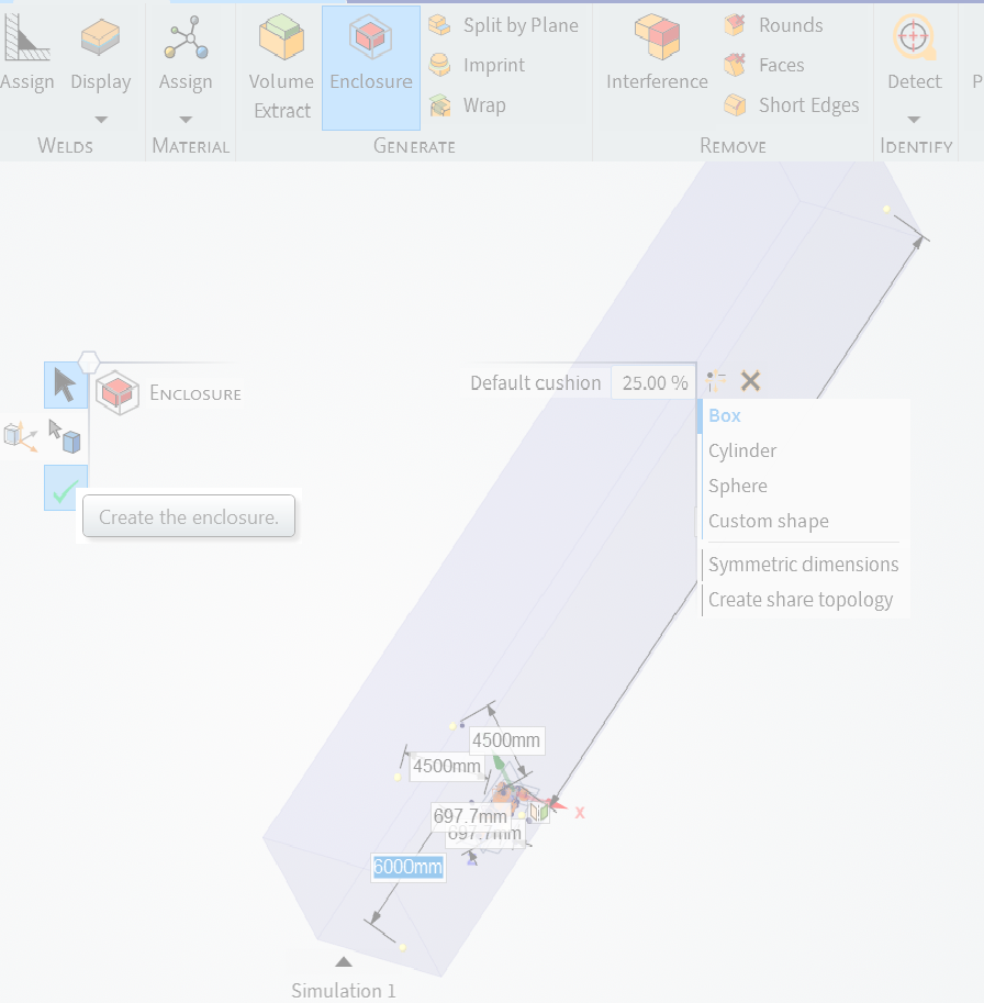 </p><p>Other functions, such as using the Interfence tool, it takes a long time for the loading mouse icon to disappear. Other function is using the pull tool to give body panels of my car some width, it's very laggy. <br>Overall, I find Ansys discovery slow.</p><p>Using Ansys 2024 R2 student, <br>My laptop specs:</p><p>13th Gen Intel(R) Core(TM) i7-13850HX<br>4000 ada 12GB<br>64GB DDR5 RAM<br>1TB SSD (~1/3 used)<br>Windows 11 Pro </p><p></p><p>Using Discovery application with tonnes of Chrome pages open, and not straining my laptop.</p><p>
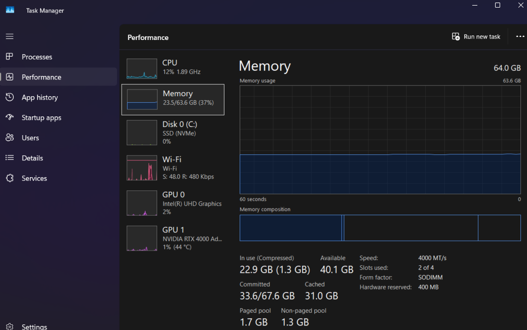 <br><br>Thanks,</p><p>Kelvin</p></p></p></p></p><br><br>Update:</p><p>I installed Ansys 2024 R2 on my other laptop (sufficient hardware to run Ansys), used the same car model as I used previously. The same error occurs.</p><p>I also tried with a simple shape, I used a cylinder, and then tried to put an enclosure around it, the same error occurs.</p><p>I will try Ansys 2025 R1, and shall update again.</p><br><br>Update 2:</p><p>I just tried using Discovery from Ansys 2025 R1 Student on my first laptop (of aforementioned), the same thing still happens!</p><p>
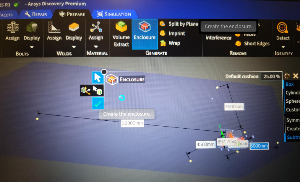 </p><p>I was thinking... it might be an issue with my Full Car Model, because using the model from preparation-using-ansys-discovery-lesson-1 , I was able to create a wind tunnel enclosure.</p><p>
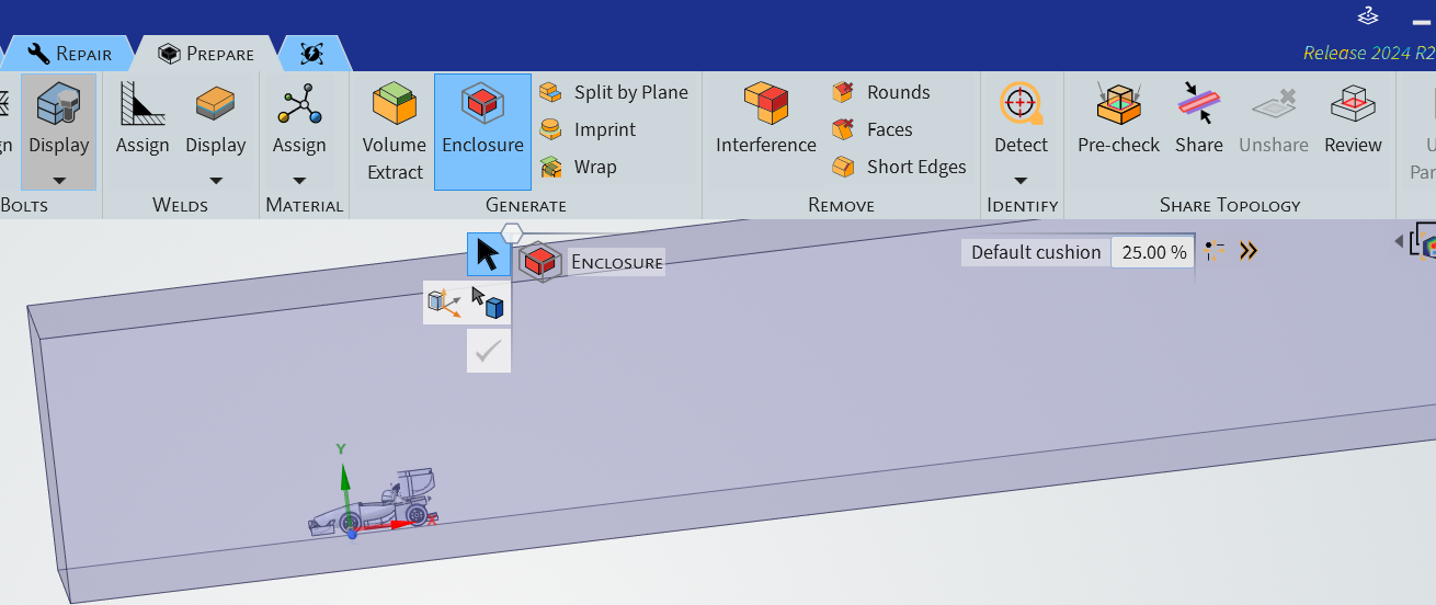 </p></p></p></p></p><p> </p><p>Could non-so-perfect body surfaces be the issues?</p></p></p>
[topic_link] => https://innovationspace.ansys.com/forum/forums/topic/ansys-discovery-freezeslags-so-much-when-certain-tasks-are-performed/
[topic_status] => publish
[topic_published_date] => May 6, 2025
[author] => kelvin.k.kong@student.uts.edu.au
[like_count] => 0
[reply_count] => 4
[view_count] => 117
)
[7] => Array
(
[topic_id] => 430870
[topic_title] => FSAE CFD – Lesson 1 Preparation question (Using Discovery)
[topic_content] => <p>Dear Ansys staff and fellow users,</p><p>In regards to the External Aerodynamic Analysis of an FSAE Car Using Ansys CFD series, Lesson 1, at about 10:07min into the video: https://www.youtube.com/watch?v=l60We_Jtvns&list=PLtt6-ZgUFmMLjplzWHZ9aObvd3n9_sBQ9&index=2</p><p>The video doesn't explain in clearly how to fill the surface in between the rim and the wheel (assuming you have you), along with removing sharp corners at the flange of the rim .</p><p>Here is the wheel from my car model I'm working on:</p><p>
</p></p></p></p></p><p> </p><p>Could non-so-perfect body surfaces be the issues?</p></p></p>
[topic_link] => https://innovationspace.ansys.com/forum/forums/topic/ansys-discovery-freezeslags-so-much-when-certain-tasks-are-performed/
[topic_status] => publish
[topic_published_date] => May 6, 2025
[author] => kelvin.k.kong@student.uts.edu.au
[like_count] => 0
[reply_count] => 4
[view_count] => 117
)
[7] => Array
(
[topic_id] => 430870
[topic_title] => FSAE CFD – Lesson 1 Preparation question (Using Discovery)
[topic_content] => <p>Dear Ansys staff and fellow users,</p><p>In regards to the External Aerodynamic Analysis of an FSAE Car Using Ansys CFD series, Lesson 1, at about 10:07min into the video: https://www.youtube.com/watch?v=l60We_Jtvns&list=PLtt6-ZgUFmMLjplzWHZ9aObvd3n9_sBQ9&index=2</p><p>The video doesn't explain in clearly how to fill the surface in between the rim and the wheel (assuming you have you), along with removing sharp corners at the flange of the rim .</p><p>Here is the wheel from my car model I'm working on:</p><p>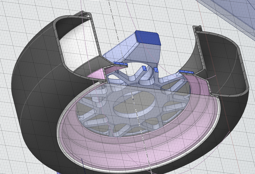 </p><p>Thanks,</p><p>Kelvin</p>
[topic_link] => https://innovationspace.ansys.com/forum/forums/topic/fsae-cfd-lesson-1-preparation-question-using-discovery/
[topic_status] => publish
[topic_published_date] => May 6, 2025
[author] => kelvin.k.kong@student.uts.edu.au
[like_count] => 0
[reply_count] => 5
[view_count] => 114
)
[8] => Array
(
[topic_id] => 430829
[topic_title] => Very slow response from DesignModeler in Ansys Workbench
[topic_content] => <p><span lang="EN-US" style="font-size: 11.0pt; font-family: 'Aptos',sans-serif; mso-fareast-font-family: Aptos; mso-fareast-theme-font: minor-latin; mso-bidi-font-family: Aptos; mso-ligatures: standardcontextual; mso-ansi-language: EN-US; mso-fareast-language: EN-US; mso-bidi-language: AR-SA;">I find some issues with using ANSYS Design modeler. It shows me not responding after every click during providing the dimensions in my geometry.</span></p>
[topic_link] => https://innovationspace.ansys.com/forum/forums/topic/very-slow-response-from-designmodeler-in-ansys-workbench/
[topic_status] => publish
[topic_published_date] => May 5, 2025
[author] => chandra.singh@lethpolytech.ca
[like_count] => 0
[reply_count] => 1
[view_count] => 87
)
[9] => Array
(
[topic_id] => 430758
[topic_title] => ANSYS Forte settings issue
[topic_content] => <p>New to this and learning reduced errors but still have this problem while setting valve inputs. A spark ingnition two valve enigne. Probably other errors too, there is a gap in the CAD model between the valve seat and the valve face of 0.5 mm. In the inputs I Exceeded limit of 500 iterations, please check boundary condition settings.<br>Ignoring update of min_lift because it is currently a Workbench parameter.<br>It must only be updated from Workbench.
</p><p>Thanks,</p><p>Kelvin</p>
[topic_link] => https://innovationspace.ansys.com/forum/forums/topic/fsae-cfd-lesson-1-preparation-question-using-discovery/
[topic_status] => publish
[topic_published_date] => May 6, 2025
[author] => kelvin.k.kong@student.uts.edu.au
[like_count] => 0
[reply_count] => 5
[view_count] => 114
)
[8] => Array
(
[topic_id] => 430829
[topic_title] => Very slow response from DesignModeler in Ansys Workbench
[topic_content] => <p><span lang="EN-US" style="font-size: 11.0pt; font-family: 'Aptos',sans-serif; mso-fareast-font-family: Aptos; mso-fareast-theme-font: minor-latin; mso-bidi-font-family: Aptos; mso-ligatures: standardcontextual; mso-ansi-language: EN-US; mso-fareast-language: EN-US; mso-bidi-language: AR-SA;">I find some issues with using ANSYS Design modeler. It shows me not responding after every click during providing the dimensions in my geometry.</span></p>
[topic_link] => https://innovationspace.ansys.com/forum/forums/topic/very-slow-response-from-designmodeler-in-ansys-workbench/
[topic_status] => publish
[topic_published_date] => May 5, 2025
[author] => chandra.singh@lethpolytech.ca
[like_count] => 0
[reply_count] => 1
[view_count] => 87
)
[9] => Array
(
[topic_id] => 430758
[topic_title] => ANSYS Forte settings issue
[topic_content] => <p>New to this and learning reduced errors but still have this problem while setting valve inputs. A spark ingnition two valve enigne. Probably other errors too, there is a gap in the CAD model between the valve seat and the valve face of 0.5 mm. In the inputs I Exceeded limit of 500 iterations, please check boundary condition settings.<br>Ignoring update of min_lift because it is currently a Workbench parameter.<br>It must only be updated from Workbench. 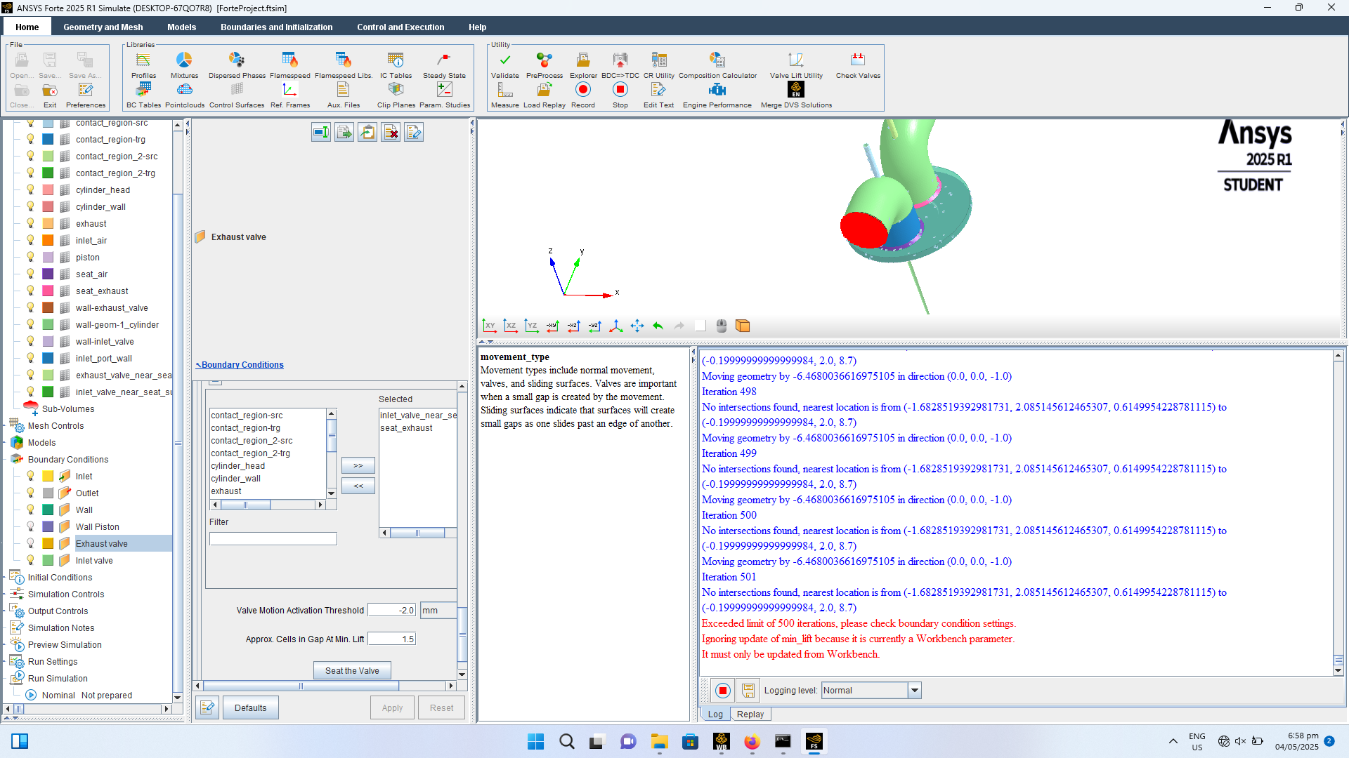 </p>
[topic_link] => https://innovationspace.ansys.com/forum/forums/topic/ansys-forte-settings-issue/
[topic_status] => publish
[topic_published_date] => May 4, 2025
[author] => Hasan
[like_count] => 0
[reply_count] => 3
[view_count] => 51
)
[10] => Array
(
[topic_id] => 430683
[topic_title] => Sign on blocked
[topic_content] => <p>Hello, </p><p>We are trying to login with the following account (<span style="font-size: 11.0pt; font-family: 'Aptos',sans-serif; mso-fareast-font-family: 'Times New Roman'; mso-bidi-font-family: Aptos; color: black; mso-ansi-language: NL; mso-fareast-language: NL; mso-bidi-language: AR-SA;">f.tesio@libellula.eu)</span>, but are getting an error. </p><p>How to unblock it?</p><p>
</p>
[topic_link] => https://innovationspace.ansys.com/forum/forums/topic/ansys-forte-settings-issue/
[topic_status] => publish
[topic_published_date] => May 4, 2025
[author] => Hasan
[like_count] => 0
[reply_count] => 3
[view_count] => 51
)
[10] => Array
(
[topic_id] => 430683
[topic_title] => Sign on blocked
[topic_content] => <p>Hello, </p><p>We are trying to login with the following account (<span style="font-size: 11.0pt; font-family: 'Aptos',sans-serif; mso-fareast-font-family: 'Times New Roman'; mso-bidi-font-family: Aptos; color: black; mso-ansi-language: NL; mso-fareast-language: NL; mso-bidi-language: AR-SA;">f.tesio@libellula.eu)</span>, but are getting an error. </p><p>How to unblock it?</p><p>  </p>
[topic_link] => https://innovationspace.ansys.com/forum/forums/topic/sign-on-blocked/
[topic_status] => publish
[topic_published_date] => May 2, 2025
[author] => paul pladet
[like_count] => 0
[reply_count] => 4
[view_count] => 67
)
)
)
)
</p>
[topic_link] => https://innovationspace.ansys.com/forum/forums/topic/sign-on-blocked/
[topic_status] => publish
[topic_published_date] => May 2, 2025
[author] => paul pladet
[like_count] => 0
[reply_count] => 4
[view_count] => 67
)
)
)
)
- Initial Code with values</p><p> - Converted the variables to parameters and now the code stops working at the line shown in red in the picture below. </p><p> </p><p> </p><p>Any ideas why this problem exists and how to solve? Thank you.</p>
[topic_link] => https://innovationspace.ansys.com/forum/forums/topic/unable-to-build-the-model-entirely-after-parameterisation/
[topic_status] => publish
[topic_published_date] => May 23, 2025
[author] => e1306841@u.nus.edu
[like_count] => 0
[reply_count] => 0
[view_count] => 2
)
[2] => Array
(
[topic_id] => 432158
[topic_title] => I missed 1 of 5 Structural Analysis classes. Is there any way to complete the se
[topic_content] => <p>I missed 1 of 5 Structural Analysis classes. Is there any way to complete the session?</p>
[topic_link] => https://innovationspace.ansys.com/forum/forums/topic/i-missed-1-of-5-structural-analysis-classes-is-there-any-way-to-complete-the-se/
[topic_status] => publish
[topic_published_date] => May 21, 2025
[author] => Young.hwangbo@honeywell.com
[like_count] => 0
[reply_count] => 1
[view_count] => 27
)
[3] => Array
(
[topic_id] => 431277
[topic_title] => ANSYS Forte port fuel injection, adding a second fuel at the inlet of piston com
[topic_content] => <p>I was looking at ANSYS Forte tutorial which uses Gasoline_1comp_49sp.cks as a fuel with the following breakdown; o2=0.1967</p><p> </p><p>h2o=0.0089</p><p> </p><p>co2=0.0192</p><p> </p><p>ic8h18=0.0562</p><p> </p><p>n2=0.7190.</p><p> </p><p>The question is how do I add another fuel to ic8h18?:Do I just change the ic8h18 fraction and add another fuel by clicking the pencil icon?</p><p> </p><p> </p><p>Tutorial link: https://ansyshelp.ansys.com/public/account/secured?returnurl=/////Views/Secured/corp/v242/en/forte_tut/i32376.html</p>
[topic_link] => https://innovationspace.ansys.com/forum/forums/topic/ansys-forte-port-fuel-injection-adding-a-second-fuel-at-the-inlet-of-piston-com/
[topic_status] => publish
[topic_published_date] => May 11, 2025
[author] => Hasan
[like_count] => 0
[reply_count] => 0
[view_count] => 107
)
[4] => Array
(
[topic_id] => 431190
[topic_title] => Why i am not able to change the Symmetric Axis
[topic_content] => <p>For some reason i am not able to change the symmetry axis for my 2D axisymmetric analysis. The system is rotating my model at Y axis instead of X axis... i have been trying to change it in the symmetry option but it is not taking it. see the attached pics..</p>
[topic_link] => https://innovationspace.ansys.com/forum/forums/topic/why-i-am-not-able-to-change-the-symmetric-axis/
[topic_status] => publish
[topic_published_date] => May 9, 2025
[author] => rajesh.parameshwariah@halliburton.com
[like_count] => 0
[reply_count] => 1
[view_count] => 65
)
[5] => Array
(
[topic_id] => 431156
[topic_title] => Discovery as external CAD option in Workbench, similar to Spaceclaim
[topic_content] => <p>Hi,</p><p>Is it possible to make the option to use as an external CAD also available to Discovery?</p><p>See screenshot below.</p><p>The reason is that now for Discovery CAD files, Mechanical makes a local copy of the CAD file, renames it to some generic SYS-... filename and points to that local copy. The link to the original CAD file is broken.<br>That is unwanted behavior. In case of Spaceclaim and the option "use a sexternal CAD" it keeps referencing to the original CAD file without making a local copy.</p><p>Ot is there another way to keep linking to the original CAD file instead of that Mechanical makes a local copy and renames it to SYS-something?</p><p>Thanks in advance!</p><p></p>
[topic_link] => https://innovationspace.ansys.com/forum/forums/topic/discovery-as-external-cad-option-in-workbench-similar-to-spaceclaim/
[topic_status] => publish
[topic_published_date] => May 9, 2025
[author] => SDB Engineering
[like_count] => 0
[reply_count] => 1
[view_count] => 49
)
[6] => Array
(
[topic_id] => 430929
[topic_title] => Ansys Discovery – Enclosure Tool, Freezes/lags when certain tasks are performed
[topic_content] => <p><p><p><p><p><p><p><p>UPDATED, I've partially figured out something is wrong with my Full Car model. But I haven't figured out a solution to fix my model. SEE BELOW<p><p><p><p><p>Dear Ansys team and fellow users,</p><p>On certain functions, in this case using the Enclosure tool. I need to make an enclosure for CFD simulation. Using Solidworks 2024 Assembly document (.SLDASM) However, after inserting the enclosure dismensions in and clicking on the green arrow, the loading circle mouse icon appears, and it doesn't seem to be able to 'unfreeze' itself. Tried 3 times, without any success. Had to force close Discovery via Task Manager.p><p></p><p>Other functions, such as using the Interfence tool, it takes a long time for the loading mouse icon to disappear. Other function is using the pull tool to give body panels of my car some width, it's very laggy. <br>Overall, I find Ansys discovery slow.</p><p>Using Ansys 2024 R2 student, <br>My laptop specs:</p><p>13th Gen Intel(R) Core(TM) i7-13850HX<br>4000 ada 12GB<br>64GB DDR5 RAM<br>1TB SSD (~1/3 used)<br>Windows 11 Pro </p><p></p><p>Using Discovery application with tonnes of Chrome pages open, and not straining my laptop.</p><p><br><br>Thanks,</p><p>Kelvin</p></p></p></p></p><br><br>Update:</p><p>I installed Ansys 2024 R2 on my other laptop (sufficient hardware to run Ansys), used the same car model as I used previously. The same error occurs.</p><p>I also tried with a simple shape, I used a cylinder, and then tried to put an enclosure around it, the same error occurs.</p><p>I will try Ansys 2025 R1, and shall update again.</p><br><br>Update 2:</p><p>I just tried using Discovery from Ansys 2025 R1 Student on my first laptop (of aforementioned), the same thing still happens!</p><p></p><p>I was thinking... it might be an issue with my Full Car Model, because using the model from preparation-using-ansys-discovery-lesson-1 , I was able to create a wind tunnel enclosure.</p><p></p></p></p></p></p><p> </p><p>Could non-so-perfect body surfaces be the issues?</p></p></p>
[topic_link] => https://innovationspace.ansys.com/forum/forums/topic/ansys-discovery-freezeslags-so-much-when-certain-tasks-are-performed/
[topic_status] => publish
[topic_published_date] => May 6, 2025
[author] => kelvin.k.kong@student.uts.edu.au
[like_count] => 0
[reply_count] => 4
[view_count] => 117
)
[7] => Array
(
[topic_id] => 430870
[topic_title] => FSAE CFD – Lesson 1 Preparation question (Using Discovery)
[topic_content] => <p>Dear Ansys staff and fellow users,</p><p>In regards to the External Aerodynamic Analysis of an FSAE Car Using Ansys CFD series, Lesson 1, at about 10:07min into the video: https://www.youtube.com/watch?v=l60We_Jtvns&list=PLtt6-ZgUFmMLjplzWHZ9aObvd3n9_sBQ9&index=2</p><p>The video doesn't explain in clearly how to fill the surface in between the rim and the wheel (assuming you have you), along with removing sharp corners at the flange of the rim .</p><p>Here is the wheel from my car model I'm working on:</p><p></p><p>Thanks,</p><p>Kelvin</p>
[topic_link] => https://innovationspace.ansys.com/forum/forums/topic/fsae-cfd-lesson-1-preparation-question-using-discovery/
[topic_status] => publish
[topic_published_date] => May 6, 2025
[author] => kelvin.k.kong@student.uts.edu.au
[like_count] => 0
[reply_count] => 5
[view_count] => 114
)
[8] => Array
(
[topic_id] => 430829
[topic_title] => Very slow response from DesignModeler in Ansys Workbench
[topic_content] => <p><span lang="EN-US" style="font-size: 11.0pt; font-family: 'Aptos',sans-serif; mso-fareast-font-family: Aptos; mso-fareast-theme-font: minor-latin; mso-bidi-font-family: Aptos; mso-ligatures: standardcontextual; mso-ansi-language: EN-US; mso-fareast-language: EN-US; mso-bidi-language: AR-SA;">I find some issues with using ANSYS Design modeler. It shows me not responding after every click during providing the dimensions in my geometry.</span></p>
[topic_link] => https://innovationspace.ansys.com/forum/forums/topic/very-slow-response-from-designmodeler-in-ansys-workbench/
[topic_status] => publish
[topic_published_date] => May 5, 2025
[author] => chandra.singh@lethpolytech.ca
[like_count] => 0
[reply_count] => 1
[view_count] => 87
)
[9] => Array
(
[topic_id] => 430758
[topic_title] => ANSYS Forte settings issue
[topic_content] => <p>New to this and learning reduced errors but still have this problem while setting valve inputs. A spark ingnition two valve enigne. Probably other errors too, there is a gap in the CAD model between the valve seat and the valve face of 0.5 mm. In the inputs I Exceeded limit of 500 iterations, please check boundary condition settings.<br>Ignoring update of min_lift because it is currently a Workbench parameter.<br>It must only be updated from Workbench. </p>
[topic_link] => https://innovationspace.ansys.com/forum/forums/topic/ansys-forte-settings-issue/
[topic_status] => publish
[topic_published_date] => May 4, 2025
[author] => Hasan
[like_count] => 0
[reply_count] => 3
[view_count] => 51
)
[10] => Array
(
[topic_id] => 430683
[topic_title] => Sign on blocked
[topic_content] => <p>Hello, </p><p>We are trying to login with the following account (<span style="font-size: 11.0pt; font-family: 'Aptos',sans-serif; mso-fareast-font-family: 'Times New Roman'; mso-bidi-font-family: Aptos; color: black; mso-ansi-language: NL; mso-fareast-language: NL; mso-bidi-language: AR-SA;">f.tesio@libellula.eu)</span>, but are getting an error. </p><p>How to unblock it?</p><p> </p>
[topic_link] => https://innovationspace.ansys.com/forum/forums/topic/sign-on-blocked/
[topic_status] => publish
[topic_published_date] => May 2, 2025
[author] => paul pladet
[like_count] => 0
[reply_count] => 4
[view_count] => 67
)
)
)
)


