TAGGED: designpoints, fluent, fluentmeshing, parametric-analysis
-
-
June 28, 2021 at 10:30 am
fabio.dinatale
SubscriberHi all,
I'm developing a parametric CFD simulation inside Ansys Workbench.
Specifically, the only parameter that changes is the angle between two of the surfaces constituting my model. The model is designed inside Ansys SpaceClaim and I am changing the orientation of the two surfaces through a SpaceClaim script in which I defined a variable which assumes the value given to the parameter. The CFD simulation process is carried out using Ansys Fluent Meshing and Ansys Fluent.
All the steps necessary for completing a CFD simulation were initially performed one by one and they work properly.
The process of generating new Design Points (duplicating the DP0), changing the value of the parameter and then update all the components for each Design Point was then implemented in order to be automatically run using a unique Workbench Journal file that I previously generated through a script. Also this process does not show any error during its execution.
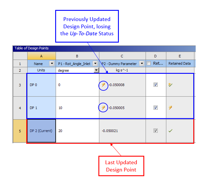
Although, I noticed that if I ask the software to perform the operation opening the related GUI (e.g. opening Ansys Fluent Meshing for generating the mesh), at the end of the update of one Design Point, all the others that were previously updated change their status into To be Updated (it appears the yellow lightning, as shown in the image below).
June 28, 2021 at 2:04 pmRahul Kumar
Ansys EmployeeHello Fabio,
May I know which version you are using?
June 28, 2021 at 2:44 pmfabio.dinatale
Subscriber
I am using Ansys Workbench 2021 R1.
Thanks Fabio
July 13, 2021 at 7:22 amfabio.dinatale
SubscriberHi all did anybody experience the same kind of issue? Do you think there exists a solution to this problem?
Thank you in advance Fabio
July 18, 2021 at 10:30 pmRahul Kumar
Ansys EmployeeHi Fabio,
I am looking to replicate the error you get but I am not able to do so. Can you please give me a step by step to replicate it?
July 19, 2021 at 9:13 amfabio.dinatale
Subscriber
in order not to make this comment too long, I decided to prepare a presentation describing the step-by-step procedure. You can find it below.
Let me know if there is something which is not clear.
I also add a zipped Workbench project that I used for doing the presentation and on which the error occurs.
Let me know if you need more data/information.
Thank you in advance for your support.
Regards Fabio
July 19, 2021 at 3:08 pmRahul Kumar
Ansys EmployeeHi Fabio Thank you very much for preparing a presentation. Unfortunately, as Ansys employees, we cannot download any files. Can you please insert the slides of the presentation as an image?
July 20, 2021 at 7:03 amfabio.dinatale
SubscriberSorry, I didn't know that you can't download files.
I report below the content of the presentation.
Geometry Definition
Open Ansys SpaceClaim and create a simple geometry (e.g. a parallelepiped), assigning the minimum required Named Selections (i.e. Inlet, Outlet, Walls). Go to Groups Tab and right-click, then select Create Script Parameter, as shown in the image below.
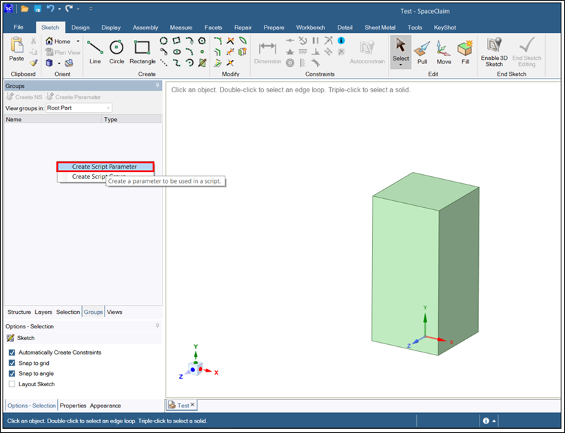 Rename the Parameter and change its type. For example, in the image on the right it is possible to see that the name of the parameter is Rotating_Angle and thus its type was changed into Angle. Indeed, the modification will be a rotation of the top face with respect to one of the side surfaces. Finally, right click again in the Groups Tab and select Create Script Group, as shown in the image below.
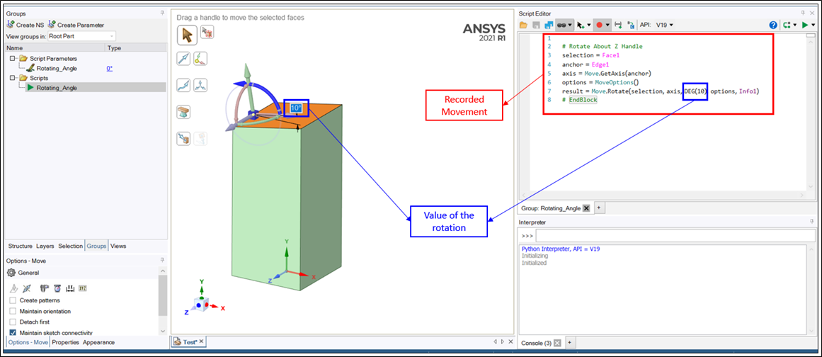
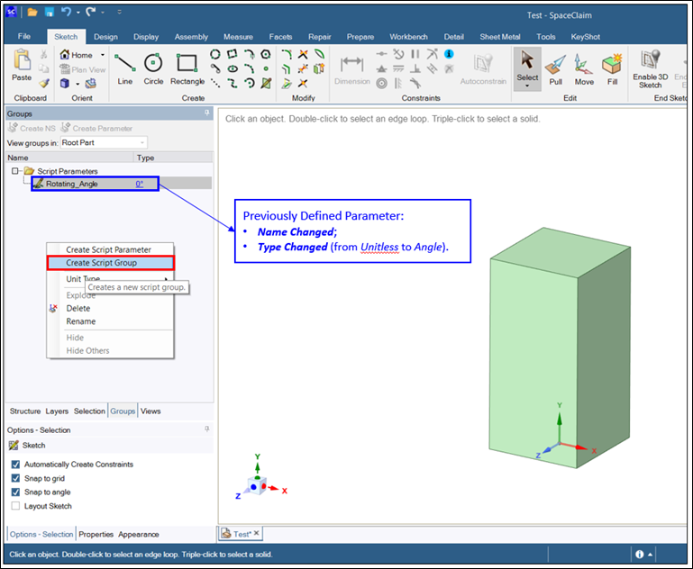 If you want, you can rename also the Script Group. Then, you can right-click on it and select Edit Script. The window on the right will open and you can start the recording, so that what you do in the Graphic Window is translated into code.
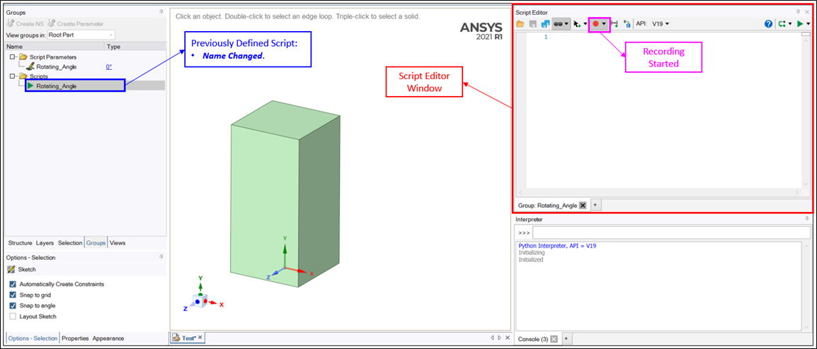 The image below shows the previously described rotation and the code that is generated because of this motion.
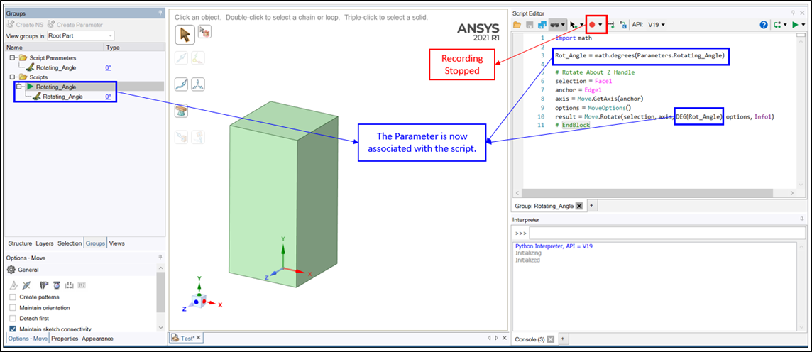
 You can finally stop the recording and manually modify the script in order to include the previously defined parameter. It is necessary to apply some transformations from radians to degrees.
 Geometry Import
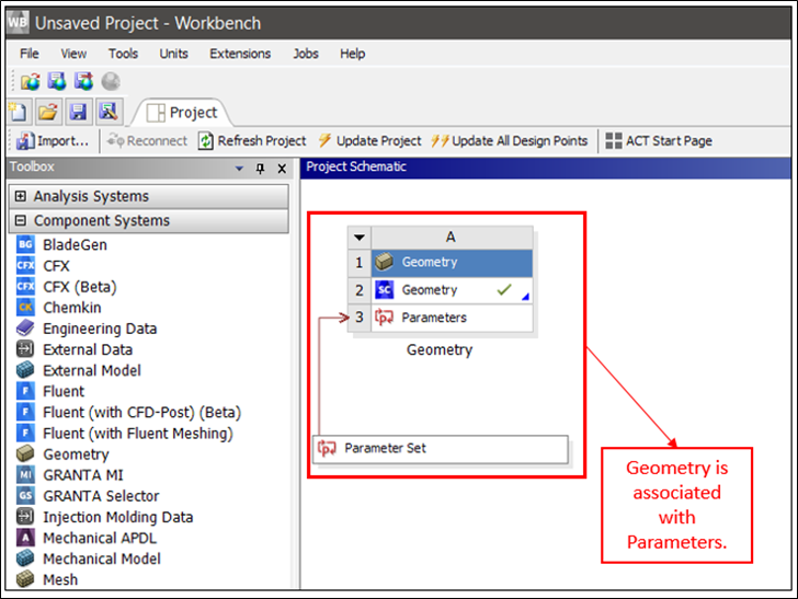
Open a Workbench project, insert a Geometry component and upload the geometry previously defined. The Parameter Set component will automatically appear (actually, after you import the geometry, you have to open it in order to make the project recognize the parameter).
 Project Definition
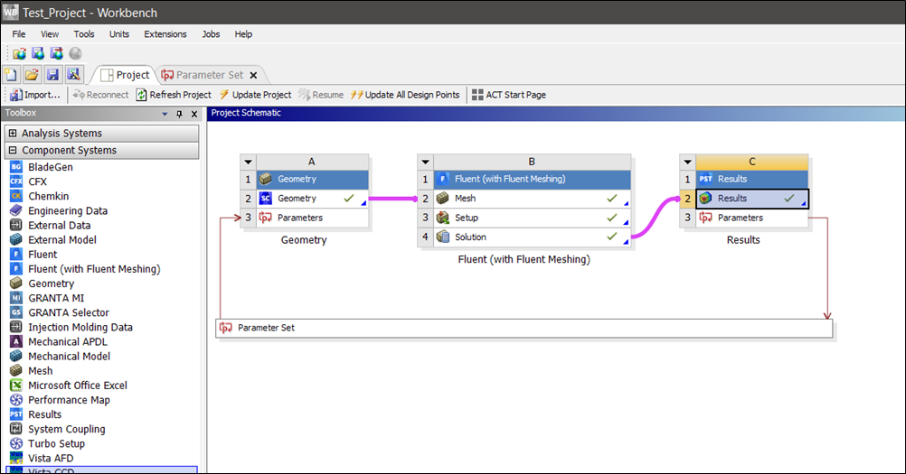
Add to the project the components Fluent (with Fluent Meshing) and Results (in particular, in this Components it is defined an Output Parameter and a Figure to be reported in the Parameter Set Tab). Update all the components, as shown in the image below.
 Design Point Creation
Create some Design Points and change the value of the geometrical Parameter.
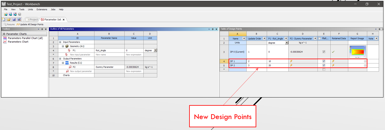 Design Point Update
Set DP1 as Current and update the Geometry Component.
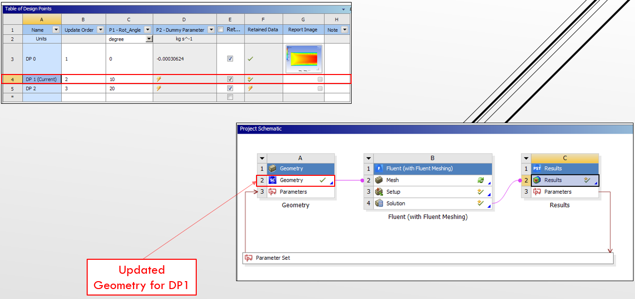 Open the Mesh Component, answering Yes to the question Do you want to refresh this cell?. Once the Mesh has been opened, you will see that DP0 is no more in the Up-to-Date status.

Sorry for the very long comment.
I hope it is clear, but please do not hesitate to ping me if there is something which is not well explained.
Thanks, Fabio
July 21, 2021 at 11:07 amRob
Forum ModeratorPart of the problem is the way the DPs are defined. As you've changed something that's linked to the input parameter WB thinks it needs to update all DPs. The issue has been raised before, but it's non-trivial to check if the parameter change alters an existing solution or not.
July 23, 2021 at 1:48 pmfabio.dinatale
SubscriberThanks for your reply.
Part of the problem is the way the DPs are defined.
Does it exist a way to define the DPs that permits to avoid the problem?
If it could be useful for understanding a possible solution to the problem, this behavior (status change) does not occur if I simply update each component (i.e.notopening the GUI).
Regards Fabio
July 23, 2021 at 3:32 pmRob
Forum ModeratorFrom memory if you just add DPs to the WorkBench table and update each manually whilst the other rows may go "out of date" the data they show is correct.
August 10, 2021 at 1:32 pmfabio.dinatale
SubscriberFrom memory if you just add DPs to the WorkBench table and update each manually whilst the other rows may go "out of date" the data they show is correct.
If I correctly understood your point, I can confirm that, even if the Status of one DP changes to "Out Of Date", the data previously calculated for the same DP still remain and they are available for Post-Processing for example.
I would like to understand if there is a solution (or if it will be developed) for this anomalous behavior.
Thanks in advance Fabio
August 12, 2021 at 9:56 amRob
Forum ModeratorI'm not aware of a solution at present, and can't comment on future developments. We are moving towards a better solution with tools like Optislang and Minerva so watch for future updates.
August 13, 2021 at 7:27 amfabio.dinatale
SubscriberThank you for your feedback and suggestion.
I will have a look to the tools you mentioned and I will be updated on future improvements about this type of solutions.
Viewing 13 reply threads- The topic ‘Why previously updated DPs change status if another DP is updated opening Ansys software GUIs?’ is closed to new replies.
Innovation SpaceTrending discussionsTop Contributors-
4728
-
1565
-
1386
-
1242
-
1021
Top Rated Tags© 2026 Copyright ANSYS, Inc. All rights reserved.
Ansys does not support the usage of unauthorized Ansys software. Please visit www.ansys.com to obtain an official distribution.
-

