-
-
December 11, 2020 at 2:34 am
paganelli9
SubscriberHi everyone, I'm trying to solve a simply torsional stiffness analysis of my FSAE team's chassis on Ansys. I actually manage to ran the model, but the results are far too unrealistic and I dont't have a clue why. I follow step by step from this video of Ansys team in how to do a chassis stiffness analysis, I only adapted for my chassis of course and I'm getting this results (link of the video: https://www.youtube.com/playlist?list=PLvsJbyBB0CMdnu9p9hZj9H7TlV3ROZ05b ). Can anyone help me? Thank you for your attention!
December 11, 2020 at 2:53 ampeteroznewman
SubscribernOne common mistake in the Engineering Data tab is to have the units set to Pa when you are typing a value in MPa or psi so you can end up with values that are 1 million times too flexible.nFor beam models, you can type cross-sectional area properties that are too small by a large factor.nEither or both of those errors can result in a force creating an enormous deformation.nIt is also possible to have the units set to the wrong value when creating the force.nDecember 11, 2020 at 6:38 pmSubscribernHi, sir! Thanks for helping me! I tried to change for MPa in the Engineering Data tab, but the results are the same. Also, can you explain me better about this cross-sectional area properties that you mentioned? I'm upploading some images with details of what I applied in boundary conditions.nRemote force on the left suspension arm (it's the same for the right arm, but with -1500N)n Simply supported at the chassis verticesn
 If you want I can upload any image from the model. Again, thank you very much for your help, it's our first time doing the torsional stiffness analysis from our chassis.n
December 11, 2020 at 8:08 pmSubscribernAnd I forget to tell: the only value that I'm adding in the model is the remote force. More images with details of the model:nThis is one of two types of joints I used, this one is revolute joint (connect the suspension arms in the chassis)n
If you want I can upload any image from the model. Again, thank you very much for your help, it's our first time doing the torsional stiffness analysis from our chassis.n
December 11, 2020 at 8:08 pmSubscribernAnd I forget to tell: the only value that I'm adding in the model is the remote force. More images with details of the model:nThis is one of two types of joints I used, this one is revolute joint (connect the suspension arms in the chassis)n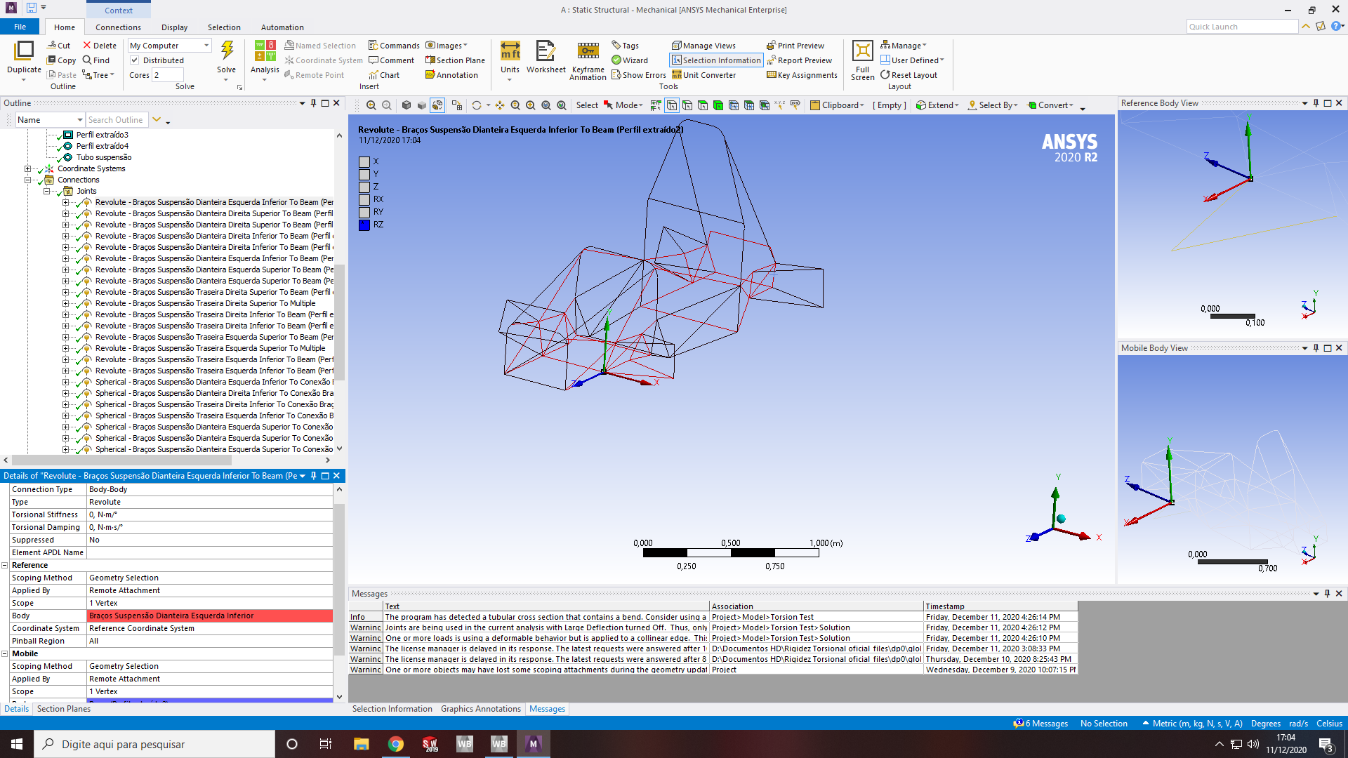 Spherical joint (connect the suspension arms in the wheel)n
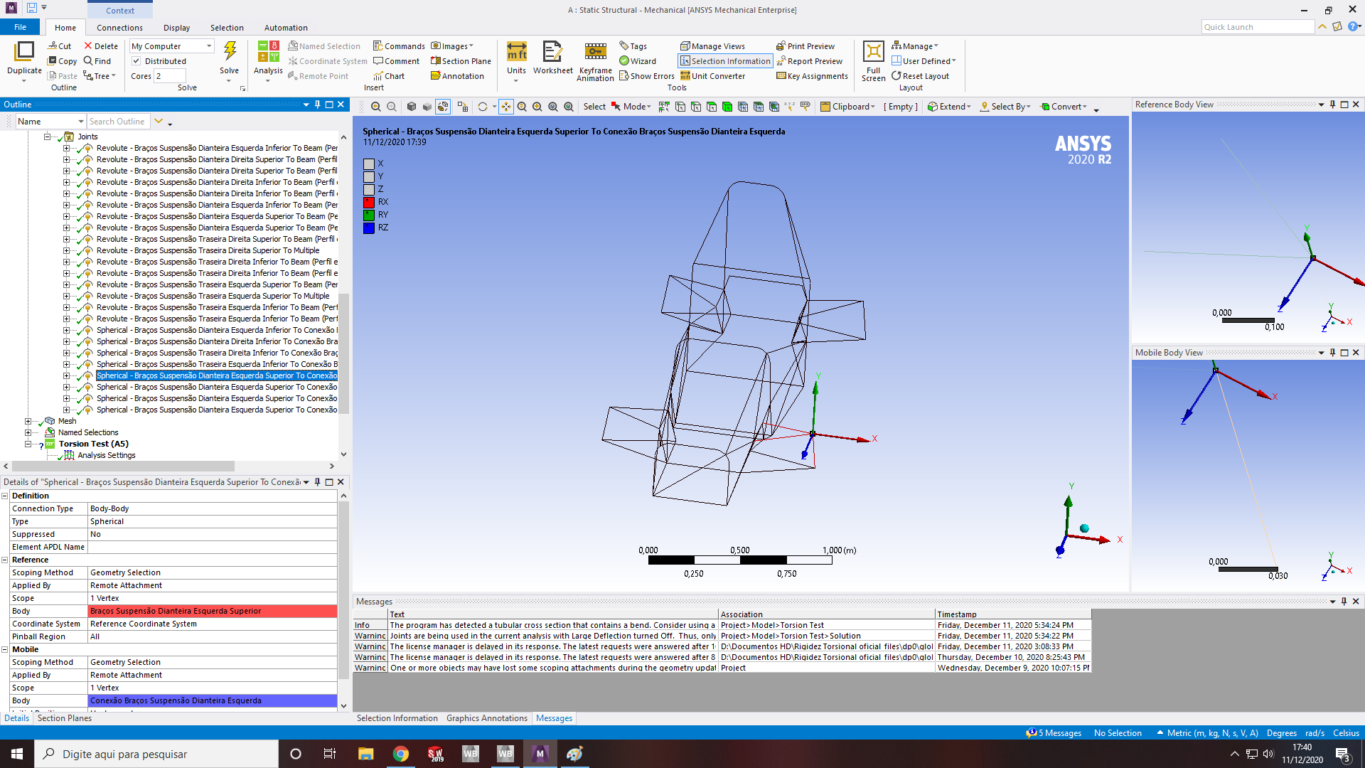 n
December 12, 2020 at 10:57 amSubscribernAh, this is the A-arm mechanism and there are spherical joints on the frame to allow the A-arms to move up and down.nOn a real car, there is a spring that builds up force as the road force at the wheel axle is applied. Do you have a spring? Adding a spring is the first corrective action for your model.nWithout a spring, there is nothing for the road force to push against, so the mechanism will go as far as it can.nStatic Structural has a feature called Weak Springs that automatically add springs to allow a mechanism to solve.nThe default for Static Structural is to use the Small Deflection assumption. With this assumption, a small motion in one direction is scaled without limit and the arm does not rotate about the joint. This model needs to use Large Deflection. Turn that on under Analysis Settings, which is the second corrective action for your model.nDecember 12, 2020 at 8:22 pmSubscriberHi, sir! Thanks for your answer! The spherical joints connects the A-arms to the wheel, not on the chassis, the joints that connects the A-arms to the chassis are the revolute joints. I turned on the weak springs and the large deflection and I actually obtained far more realistic results, but I'm having some errors and warnings messages that I think it's related to the file. I will attached the images.nThe results are more realistics:n
n
December 12, 2020 at 10:57 amSubscribernAh, this is the A-arm mechanism and there are spherical joints on the frame to allow the A-arms to move up and down.nOn a real car, there is a spring that builds up force as the road force at the wheel axle is applied. Do you have a spring? Adding a spring is the first corrective action for your model.nWithout a spring, there is nothing for the road force to push against, so the mechanism will go as far as it can.nStatic Structural has a feature called Weak Springs that automatically add springs to allow a mechanism to solve.nThe default for Static Structural is to use the Small Deflection assumption. With this assumption, a small motion in one direction is scaled without limit and the arm does not rotate about the joint. This model needs to use Large Deflection. Turn that on under Analysis Settings, which is the second corrective action for your model.nDecember 12, 2020 at 8:22 pmSubscriberHi, sir! Thanks for your answer! The spherical joints connects the A-arms to the wheel, not on the chassis, the joints that connects the A-arms to the chassis are the revolute joints. I turned on the weak springs and the large deflection and I actually obtained far more realistic results, but I'm having some errors and warnings messages that I think it's related to the file. I will attached the images.nThe results are more realistics:n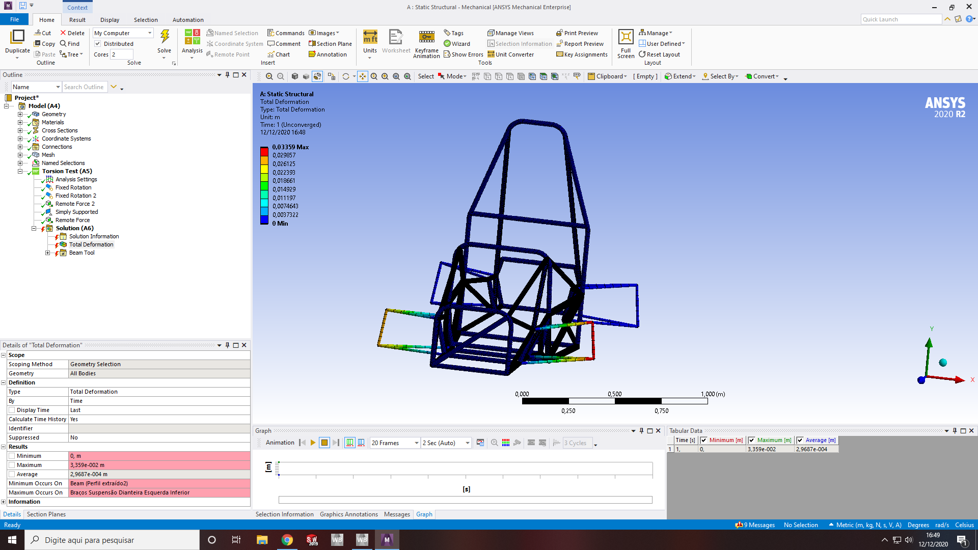 Error message:n
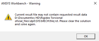
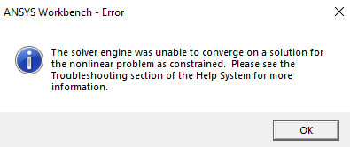 Warning messages:n
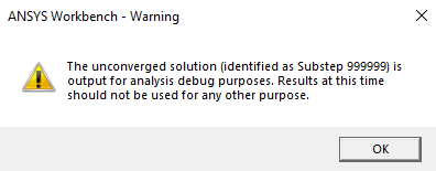
 (I already tried to Clear the Generated Data in Solution, but receive the same message above)n
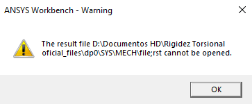 It was all this messages that appeared. You know what I can do for solutionate this and run all the simulation? Again, thank you very very much for your help sir!n
December 12, 2020 at 10:20 pmSubscriberArraynLook at the posts in the Google search of this site for the term unable to converge. There are many standard methods to resolve this situation.nhttps://www.google.com/search?q=site%3Aforum.ansys.com+%22unable+to+converge%22nDecember 14, 2020 at 8:35 pmSubscriberArraynHi sir! Thanks for helping me. So I tried a lot of different informations that I found in the link that you posted above, but I still couldn't run the model. So I put some Newton-Raphson Residual Force to check where the problem is and I find thesen
It was all this messages that appeared. You know what I can do for solutionate this and run all the simulation? Again, thank you very very much for your help sir!n
December 12, 2020 at 10:20 pmSubscriberArraynLook at the posts in the Google search of this site for the term unable to converge. There are many standard methods to resolve this situation.nhttps://www.google.com/search?q=site%3Aforum.ansys.com+%22unable+to+converge%22nDecember 14, 2020 at 8:35 pmSubscriberArraynHi sir! Thanks for helping me. So I tried a lot of different informations that I found in the link that you posted above, but I still couldn't run the model. So I put some Newton-Raphson Residual Force to check where the problem is and I find thesen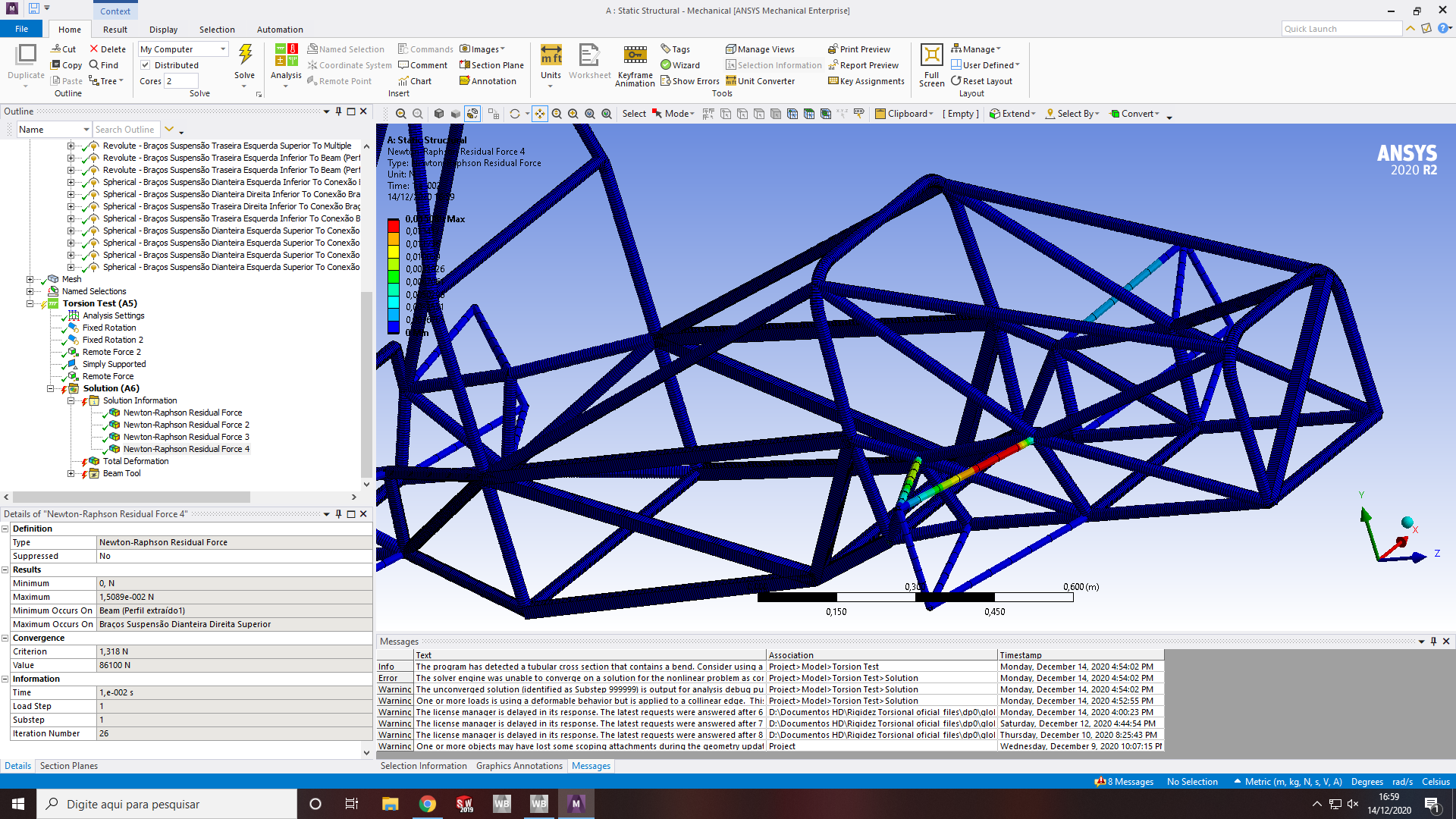
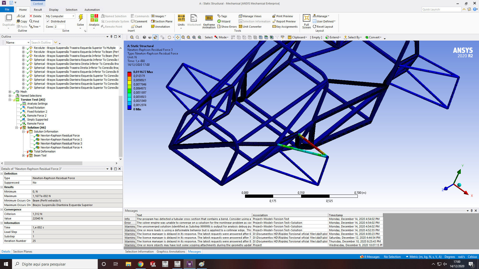 Do you know what I can change in my model to solve this?nI'm also upploading the project archive if you wanna take a look.nArrayAgain, thank you very very much, Peter! Have a great day!n
December 14, 2020 at 10:52 pmSubscribernYou missed my point about having to add springs in the A-arm mechanism to prevent them from being floppy.nSince you didn't add springs, I changed all the revolute and spherical joints to fixed joints to prevent the A-arm mechanisms from being floppy.nI picked one rear A-arm to be simply supported in XYZ, another to be supported in YZ and one front A-arm to be supported in Y. I applied a Force on the opposite A-arm of 3000 N and solved to find out the amount of twist in the frame. This is one way to measure torsional stiffness. If you want to clamp the frame the way you did and push up and down on the two A-arms with 1500 N, you can do that instead.nnDecember 15, 2020 at 2:38 amSubscriberArraynHi sir! I actually saw your explanation about the springs, that's why I added the Weak Springs like you recommended.nOur car have springs, but they are mounted like this:n
Do you know what I can change in my model to solve this?nI'm also upploading the project archive if you wanna take a look.nArrayAgain, thank you very very much, Peter! Have a great day!n
December 14, 2020 at 10:52 pmSubscribernYou missed my point about having to add springs in the A-arm mechanism to prevent them from being floppy.nSince you didn't add springs, I changed all the revolute and spherical joints to fixed joints to prevent the A-arm mechanisms from being floppy.nI picked one rear A-arm to be simply supported in XYZ, another to be supported in YZ and one front A-arm to be supported in Y. I applied a Force on the opposite A-arm of 3000 N and solved to find out the amount of twist in the frame. This is one way to measure torsional stiffness. If you want to clamp the frame the way you did and push up and down on the two A-arms with 1500 N, you can do that instead.nnDecember 15, 2020 at 2:38 amSubscriberArraynHi sir! I actually saw your explanation about the springs, that's why I added the Weak Springs like you recommended.nOur car have springs, but they are mounted like this:n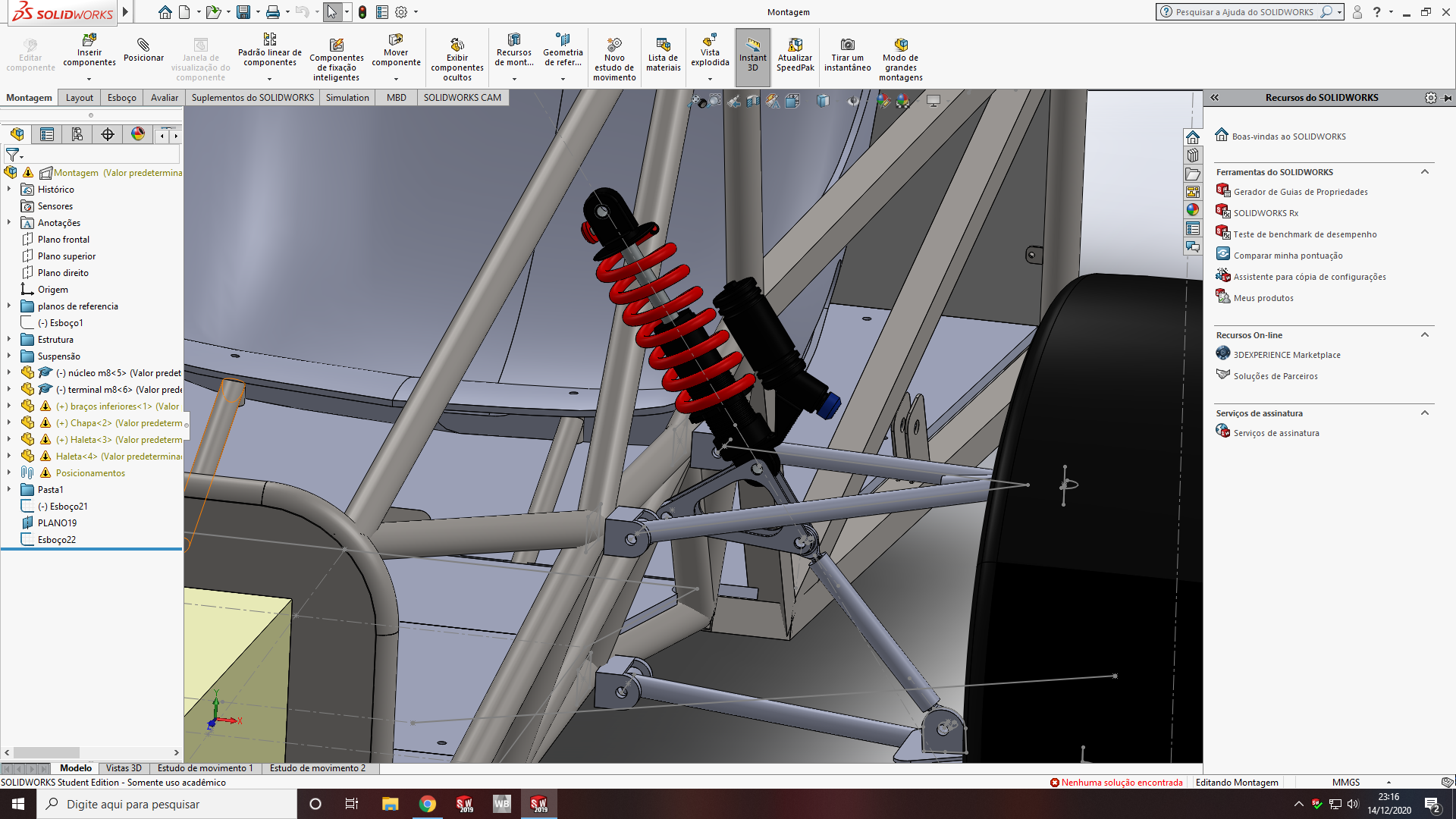 And I don't have a clue how to represent this in Ansys. I know how to put a spring, but only in a direct way (chassis to A-arm), not how it's in the picture. Do you know how I can represent this in Ansys?nThanks for your time and help, Peter!n
December 15, 2020 at 2:52 amSubscribernWeak springs are 1E-6 times smaller than the spring you need, so they may as well not be present. You need to put an actual spring into the mechanism.nThe image you show has two extra links: one a simple strut and another has three revolute joints. If you add those, then you can add the spring from the third point on that link to the fixed point on the frame.nDecember 21, 2020 at 6:21 pmSubscriberArray nHi sir! In the last few days I was trying to do what you told me, but I'm having a trouble to import the rocker (or bell crank) vertices (points) to workbench for create the joints in the mechanical and then add the springs of our car.n
And I don't have a clue how to represent this in Ansys. I know how to put a spring, but only in a direct way (chassis to A-arm), not how it's in the picture. Do you know how I can represent this in Ansys?nThanks for your time and help, Peter!n
December 15, 2020 at 2:52 amSubscribernWeak springs are 1E-6 times smaller than the spring you need, so they may as well not be present. You need to put an actual spring into the mechanism.nThe image you show has two extra links: one a simple strut and another has three revolute joints. If you add those, then you can add the spring from the third point on that link to the fixed point on the frame.nDecember 21, 2020 at 6:21 pmSubscriberArray nHi sir! In the last few days I was trying to do what you told me, but I'm having a trouble to import the rocker (or bell crank) vertices (points) to workbench for create the joints in the mechanical and then add the springs of our car.n December 21, 2020 at 9:01 pmSubscribernUse two Mechanical Models, one for the Chassis frame, one for the A-arm mechanism. Each one has its own mesh. You could even have three Mechanical Models if necessary. Link them into another Mechanical Model where the Revolute Joints can be defined. Then link that into a Static Structural where the loads and support can be defined.n
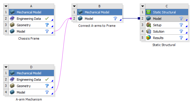 n
December 28, 2020 at 9:14 pmSubscriberArraynHi Sir! Sorry for the delay, I was trying to run the model this past days. So I managed to overcome the issue above by just clicking in Clear Generated Data from the Model and move on. Then I made the rocker (bell crank) of the spring and set all joints, but I'm receiving the same message. I already reviewed the model and all the joints to see if they match with reality and they are matching, so I don't have a clue what's going on. I also changed all the joints for FIXED just to see what would happen like you did and then I could run the model and I actually obtained some very reasonable results, but I think that by setting all the joints as FIXED my simulation would not represent the reality. Do you know if I can let the joints as FIXED to make a chassis torsional stifness analysis? Beside, I'm upploading my model as it is today if you wanna take a look, with the joints sets as I think they have to be set. Again, I really apreciate your help mr. Peter! Thank you very very much!nArraynDecember 28, 2020 at 9:44 pmSubscriberArraynHi sir! Sorry for the delay, in this past few days I was trying to run the model. So I overcome the issue above by clicking in Clear Generated Data in the Model and move on. Then I made the rocker (bell crank) of the spring system and set all the joints in the way I think they should be, representing the reality, but I couldn't run the model, I'm receiving the same message. I already checked to see if all the joints were set in the right way representing the reality and they are, I don't have a clue what's going on. I also changed all the joints to FIXED like you did to see if the model would run and it did, the results were also very reasonable from what we expect from the chassis stiffness, but I think that if we set all joints to FIXED we would not representing reality. Do you know if I can make a chassis torsional stiffness analysis with all joints set as FIXED? Beside, I'm upploading my model as it is today if you wanna take a look, with the joints sets as I think they have to be set. Again, I really apreciate your help mr. Peter! Thank you very very much for your support!nArraynDecember 28, 2020 at 10:48 pmSubscribernAn evaluation of the Chassis Torsional Stiffness will be acceptable with all the joints set to Fixed.nIf you allow the A-arms to be loaded with a spring, and to deform when applying load to the wheel axle in an attempt to deform the chassis, well, now you have two springs in series, the A-arm spring and the chassis equivalent spring stiffness. Why would you want to muddle them together. The spring rate on the A-arm has nothing to do with the chassis stiffness, does it?nDecember 28, 2020 at 11:27 pmSubscriberArray nHi sir! So I don't think that the spring rate on the A-arm has something to do with the chassis stiffness, I actually saw a lot of torsional stiffness analysis with a lot less information than my model. I ran the model with all joints set to FIXED, but with the boundary conditions that you set before, but I don't think the results are reasonable in the chassis area.n
n
December 28, 2020 at 9:14 pmSubscriberArraynHi Sir! Sorry for the delay, I was trying to run the model this past days. So I managed to overcome the issue above by just clicking in Clear Generated Data from the Model and move on. Then I made the rocker (bell crank) of the spring and set all joints, but I'm receiving the same message. I already reviewed the model and all the joints to see if they match with reality and they are matching, so I don't have a clue what's going on. I also changed all the joints for FIXED just to see what would happen like you did and then I could run the model and I actually obtained some very reasonable results, but I think that by setting all the joints as FIXED my simulation would not represent the reality. Do you know if I can let the joints as FIXED to make a chassis torsional stifness analysis? Beside, I'm upploading my model as it is today if you wanna take a look, with the joints sets as I think they have to be set. Again, I really apreciate your help mr. Peter! Thank you very very much!nArraynDecember 28, 2020 at 9:44 pmSubscriberArraynHi sir! Sorry for the delay, in this past few days I was trying to run the model. So I overcome the issue above by clicking in Clear Generated Data in the Model and move on. Then I made the rocker (bell crank) of the spring system and set all the joints in the way I think they should be, representing the reality, but I couldn't run the model, I'm receiving the same message. I already checked to see if all the joints were set in the right way representing the reality and they are, I don't have a clue what's going on. I also changed all the joints to FIXED like you did to see if the model would run and it did, the results were also very reasonable from what we expect from the chassis stiffness, but I think that if we set all joints to FIXED we would not representing reality. Do you know if I can make a chassis torsional stiffness analysis with all joints set as FIXED? Beside, I'm upploading my model as it is today if you wanna take a look, with the joints sets as I think they have to be set. Again, I really apreciate your help mr. Peter! Thank you very very much for your support!nArraynDecember 28, 2020 at 10:48 pmSubscribernAn evaluation of the Chassis Torsional Stiffness will be acceptable with all the joints set to Fixed.nIf you allow the A-arms to be loaded with a spring, and to deform when applying load to the wheel axle in an attempt to deform the chassis, well, now you have two springs in series, the A-arm spring and the chassis equivalent spring stiffness. Why would you want to muddle them together. The spring rate on the A-arm has nothing to do with the chassis stiffness, does it?nDecember 28, 2020 at 11:27 pmSubscriberArray nHi sir! So I don't think that the spring rate on the A-arm has something to do with the chassis stiffness, I actually saw a lot of torsional stiffness analysis with a lot less information than my model. I ran the model with all joints set to FIXED, but with the boundary conditions that you set before, but I don't think the results are reasonable in the chassis area.n The Ansys Learning Forum is a public forum. You are prohibited from providing (i) information that is confidential to You, your employer, or any third party, (ii) Personal Data or individually identifiable health information, (iii) any information that is U.S. Government Classified, Controlled Unclassified Information, International Traffic in Arms Regulators (ITAR) or Export Administration Regulators (EAR) controlled or otherwise have been determined by the United States Government or by a foreign government to require protection against unauthorized disclosure for reasons of national security, or (iv) topics or information restricted by the People's Republic of China data protection and privacy laws.
Please Login to Report Topic
Please Login to Share Feed
Edit Discussion
[bingo_chatbox]The Ansys Learning Forum is a public forum. You are prohibited from providing (i) information that is confidential to You, your employer, or any third party, (ii) Personal Data or individually identifiable health information, (iii) any information that is U.S. Government Classified, Controlled Unclassified Information, International Traffic in Arms Regulators (ITAR) or Export Administration Regulators (EAR) controlled or otherwise have been determined by the United States Government or by a foreign government to require protection against unauthorized disclosure for reasons of national security, or (iv) topics or information restricted by the People's Republic of China data protection and privacy laws.
-
General Mechanical
Topics related to Mechanical Enterprise, Motion, Additive Print and more.
Why my deformation is unrealistic? (too large)

