-
-
July 9, 2023 at 8:14 am
schejarla
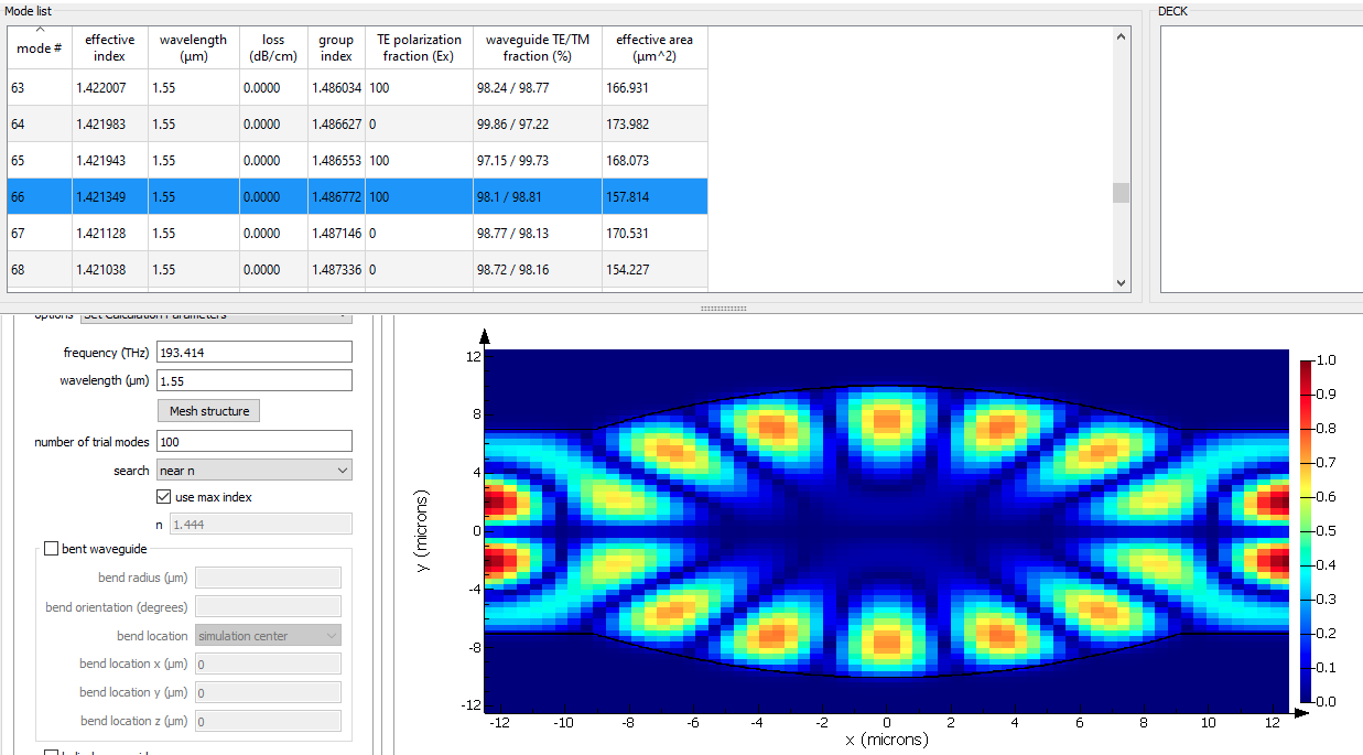
SubscriberPlease see the below screen shot which has two different results solved from two different eigen mode solvers
- FEM solver in comsol
- FDE eigen mode solver in Lumerical
The results from the Comsol FEM are promising with the our physics and the mathematical modeling. But when we go for the same study in Lumerical FDE eigen mode solver, we see completely different results. Why the results are differemt ? Please kindly suggest and give your inputs on this.
The FEM comsol results are based on 2D axi-symmetric structure using weak-form PDE where as the Lumerical structure is 3D.
The mesh size in comsol is 5 nm and the mesh size in Lumerical is 1 pm. The boundary conditions used in comsol are PML and where as in Lumerical I tried with Metal and PML both.
-
July 10, 2023 at 7:02 pm
Guilin Sun
Ansys EmployeeI believe this is not due to meshing. It is the coordinate system that matters. For the same mode, when viewing in Cartesian and cyliderical coordinate systems they may look different. Lumerical FDE shows the results in Cartisian coordinate system. You could transform it into cylinderical system by referring some transorm expressions. Not only the coordinate system, but also the naming of the modes can also be different.
You said Lumericle uses 1pm? please chek it again. You do not need too fine mesh at optical frequency. the first mode seems about 20*20um it is hard to believe 1pm mesh is used as the image shows clearly the discrete data.
-
July 11, 2023 at 7:26 am
schejarla
SubscriberThank you fro your suggestion. Sorry for the confusion about the mesh size. Please look at the below results for a mesh size of 98 nm.
I see a difference in the results in cylindrical co-ordinate system but they are not proper modes as like as cartesian co-or. But What I understand is the eigen mode solver solves Maxwells equations in the respective co-ordinate system based on the symmetry of the structure that whatever the structure we create. If it is cylindrical symmetry, the solver solves in cylindrical co-or sys. Am I correct ? The x,y and z axes are just for the representation of geometrical co-ordinates. Please clarify.
I tried searching for 500 modes and looking for the higher order mode corresponding to lower effective index.
I see some closure results as similar as Comsol results but the extra garbage fields are coming in the straight waveguide region. How to reduce these fields ? What should be the cause of this ?
-
July 11, 2023 at 11:33 pm
Guilin Sun
Ansys EmployeeAs shown by the images, they do not have the same simulation region. FDE used metal BCs so the mode you are seeing might not be the actual propagating mode. Instead it might be the box mode formed by the metal BCs.
The modes are very tight in terms of effective index (very similar to the whisper gallery modes). therefore you will need to make sure this is the mode to be compared.
You are right that ” the eigen mode solver solves Maxwells equations in the respective co-ordinate system” however it is not based on the symmetry of the structure, except that you specify the symmetry BCs.
One coordinate system is a projection/transformation of another, so the mode profile may not be necessarily the same.
Please make sure you use exactly the same frequency.
-
July 12, 2023 at 7:36 am
schejarla
SubscriberSorry, I didn't understand the simulation region, you meant for selecting the whole waveguide or only the portion of the region where the circular bulge is there? The FDE selects only the cross sectional region, not the entire 3D geometry.
Which boundary conditions must be used here ? please suggest metal or PML? How to use the symmetric BCs ?
Yes, the frequency is same.
Have a doubt regarding mesh, currently I am using a selective meshing for the circular bulge of the waveguide, Should I use this selective meshing in whole 3D region or until the FDE region is fine ?
Still no improvements in my results.!
-
July 17, 2023 at 10:29 am
schejarla
SubscriberDear Lumerical support,
Please kindly reply.
-
July 17, 2023 at 4:35 pm
Guilin Sun
Ansys EmployeeI am sure this was replied. unfortunately the system did not catch it up, which can happen sometimes. sorry about that.
FDE definitely only simualtes a cross section of a waveguide. it is not 3D solver. In your case if the horizontal geometry is a cylinder, not a rectangle, you will need to use 3D FDTD to simulate such cavity. In case you only need to simulate 2D cross section to get some idea, please consider using the same dimension as the 3rd party, and similar boundary conditions. What you got currently is more like a metal box mode. In addition it looks like such mode is similar to the whisper garllery mode, which has many different modes with small wavelength spacing and very close neff. therefore you will need to carefully set the simulation region, mesh and boundary conditions, as well as looking for higher order modes to identify the true propagation or cavity mode.
You can use either PML or metal BCs. However to know which one is the correct mode using metal BCs, you will need to change the simulation dimensions and see if the mode profile and neff chage. For PML, you may need to have more number of trial modes to get out off PML modes.
The frequency you use is not the same as in the first post you use 193.11THz and in FDE you use 193.414THz. Please note that Lumerical does not use the norminal light speed, it uses the real speed in vacuum:299792458 m/s based on permittivity and permeability. Therefore conversion of wavelength to frequency will be different from the norminal speed. Bear in mind that the acutal quantity used in the solver is frequency, not the wavelength.
"selective mesh" is not Lumerical's concept.
Please modify the settings and try different simulation dimension and boundary conditions and make sure the solver is correct for such simulation: cavity or waveguide?
-
July 18, 2023 at 4:50 am
schejarla
SubscriberThank you so much for your valaubale suggestions. I will try them out and get back to you. What about symmetric BCs ? Does it critical in my case? If yes, How do I implement them ?
-
July 18, 2023 at 4:27 pm
Guilin Sun
Ansys EmployeePlease refer to this article: https://optics.ansys.com/hc/en-us/articles/360034382694-Symmetric-and-anti-symmetric-BCs-in-FDTD-and-MODE
It will select the modes that have such summetry, and save memory as well as time.
-
July 24, 2023 at 11:33 am
schejarla
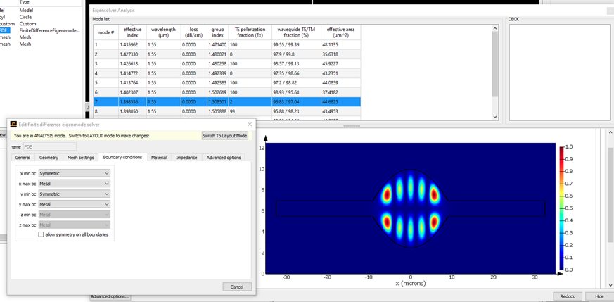
SubscriberI have used the symmetric boundary conditions to solve only portion (upper-half) of the waveguide, please see the below figures
I have got some reasonable results but the dimension of the designed wavegyuide are different after FDE solver as shown below. Why is it so?
Do I need to select the FDTD whole region of the waveguide (not only the upper-part)? Please kindly clarify. I am trying for the similar modes of more higher order.
-
July 24, 2023 at 5:25 pm
Guilin Sun
Ansys EmployeeI am glad that you finally got some reasonable result.
It is the display that shows you the whole mode profile with symmetry-type of BCs.
Since you have used symetrical/symmetrical BCs the mode has such behavior. Please make sure that this is the mode property you desired.
FDE is to solve the mode profile for a waveguide cross section, which is usually 2D while the waveguide is 3D, and the 3rd dimension is infinitely long.
FDTD, on the other hand, can simulate actual 3D cavity. To find desired 3D modes, you can use specific symmetry BCs, proper dipole clouds and monitor groups. Since it is time-domain method, what you find is the resonant modes/frequencies, which may not show you the desired frequency (it depends on the mesh accuracy). The resonant frequency is the simulated result, not the pre-specified value. You can limit the excitation/analysis bandwidth. This will be another topic. If you have questions, please write a new post.
-
July 25, 2023 at 7:45 am
schejarla
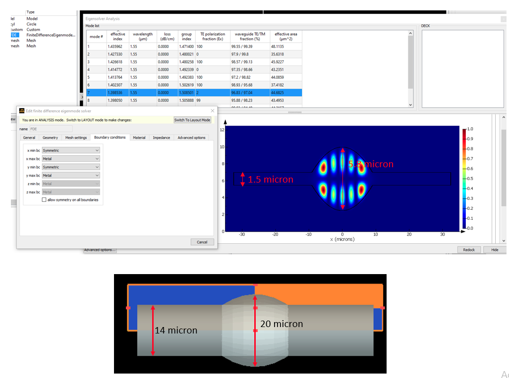
SubscriberSorry, I did not undesrtand why the dimension is shrinking after the FDE solver.
It is nearly becomning half of the original diamater at the centere and the straight waveguide is shrinked to 1 micron from 14 micron original diamter. Please kindly clarify.
-
July 25, 2023 at 3:55 pm
Guilin Sun
Ansys EmployeeIt is hard to believe the dimension can be shrinking in FDE solver. Please check the original dimension and use the ruler on the left panel to roughly measure the size. From your screencopy, the rectangle has x-span roughly 70um, and center y span (about the diameter) about 7um including the rectangle y-span.
-
July 26, 2023 at 4:44 pm
schejarla
SubscriberI have measured the dimensions, please check the screen shot
I have defined the FDTD solver for the upper half of the structure since the structure is symmetric. But I could not find any relation between the original dimensions and the shrinking dimensions. Please kindly clarify with clear explanations. Thank you.
-
July 28, 2023 at 8:53 pm
Guilin Sun
Ansys EmployeeMay I know where you define the dimensions? are they inside a structure group or inside "model"? please check geometry and compare the dimension. I have not seen any report that the simulated dimension is such different from the original setting. The only reason I know of is, the actual dimension is set somewhere through a group.
You can do a simple test with a rectagle waveguide only and make sure the dimension does not change. Or you can copy the correct geometry with material to a new project file, which will get rid of "model" control. You can also post some geometry settings here.
-
July 30, 2023 at 8:30 am
schejarla
SubscriberI got it, it is beacuse of the FDTD and symmetric BCs are defiend only for the half of the structure, due to that the lower portion of the BCs is taken as same as the upper portion where the FDTD is defined.
I think, it is not possible to see the similar modes as like as the third party (Comsol multiphysics) since Lumerical is taking the structure as waveguide and the propagation is normal to the FDTD plane.But I am interested in propagation modes along the x-direction and wanted study the longitudinal modes in the x-y plane. I am not interested in the transverse plane.
Can you please clarify where is the excitation point defined exactly for my structure as per the FDE eigen mode solver ? Is it defined from the end of straight waveguide ? or Some where in the middle?
-
July 31, 2023 at 2:54 pm
Guilin Sun
Ansys EmployeeFDE solves mode profiles of an infinite waveguide, which is on a cross section.
Yours is a cavity, as I pointed out previously it is similar to WGM. Thus you need to excite the cavity and pick up the correct modes. Maybe the 3rd party can solve cavity modes. But FDE is only from waveguide cross section, not for cavity. Only 3DFDTD can simulate 3D cavity. Please refer WGM examples online.
FDE calculates the modes at any cross section you specified. It assumes 3rd dimension is infinite.
I hope this clarifies.
-
August 1, 2023 at 6:11 am
schejarla
SubscriberThank you so much for your patience. I will try in 3D FDTD.
-
- The topic ‘Why FDE Eigen mode solver is giving different solution than Comsol FEM solver?’ is closed to new replies.


-
4838
-
1587
-
1386
-
1242
-
1021

© 2026 Copyright ANSYS, Inc. All rights reserved.


