I simulated an electromagnet using Maxwell. Compared with the measured data, the agreement was quite good at the initial stage, but in the later stage, the force increased proportionally with the current, which is inconsistent with the actual situation.
DT4E is the material actually used. As can be seen, the curve was fine at first, but the force kept increasing linearly in the later stage. When a current of 100A was applied, I just got a 1400N force, and there’s no saturation trend at all. Since the B-H curve of this material was imported from the supplier, I suspected there might be some issues with the custom B-H curve, so I tried Ansys' built-in material 1008 steel, which also has a B-H curve. It can be seen that the overall trend remained unchanged, and a force of about 1200N was obtained at 100A in the end. This means the custom material's B-H curve has no problem? So where is the issue?
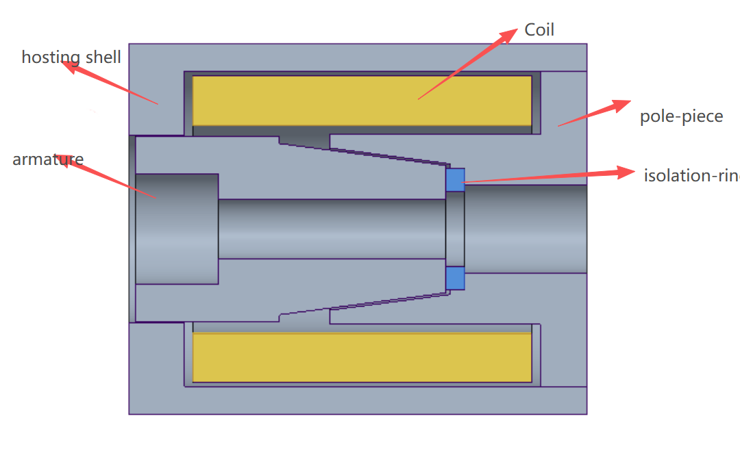
I used magnetostatic simulation. The structure of the electromagnet is shown in the figure below. The coil has an equivalent number of turns of 540, type: standard. The sweep current ranges from 0 to 12A, and the parameters are set to analyze the force on the armature. The coil material is assigned as copper, the isolation as stainless steel, and the rest as DT4E. The region has a 50% extension assigned as air. So where is the issue? What should I do next? It’s my first time using Maxwell. I read a lot of lessons before the simulation—are there any key steps I missed?


