TAGGED: friction, newton-raphson-residuals
-
-
December 24, 2021 at 11:27 am
Rameez_ul_Haq
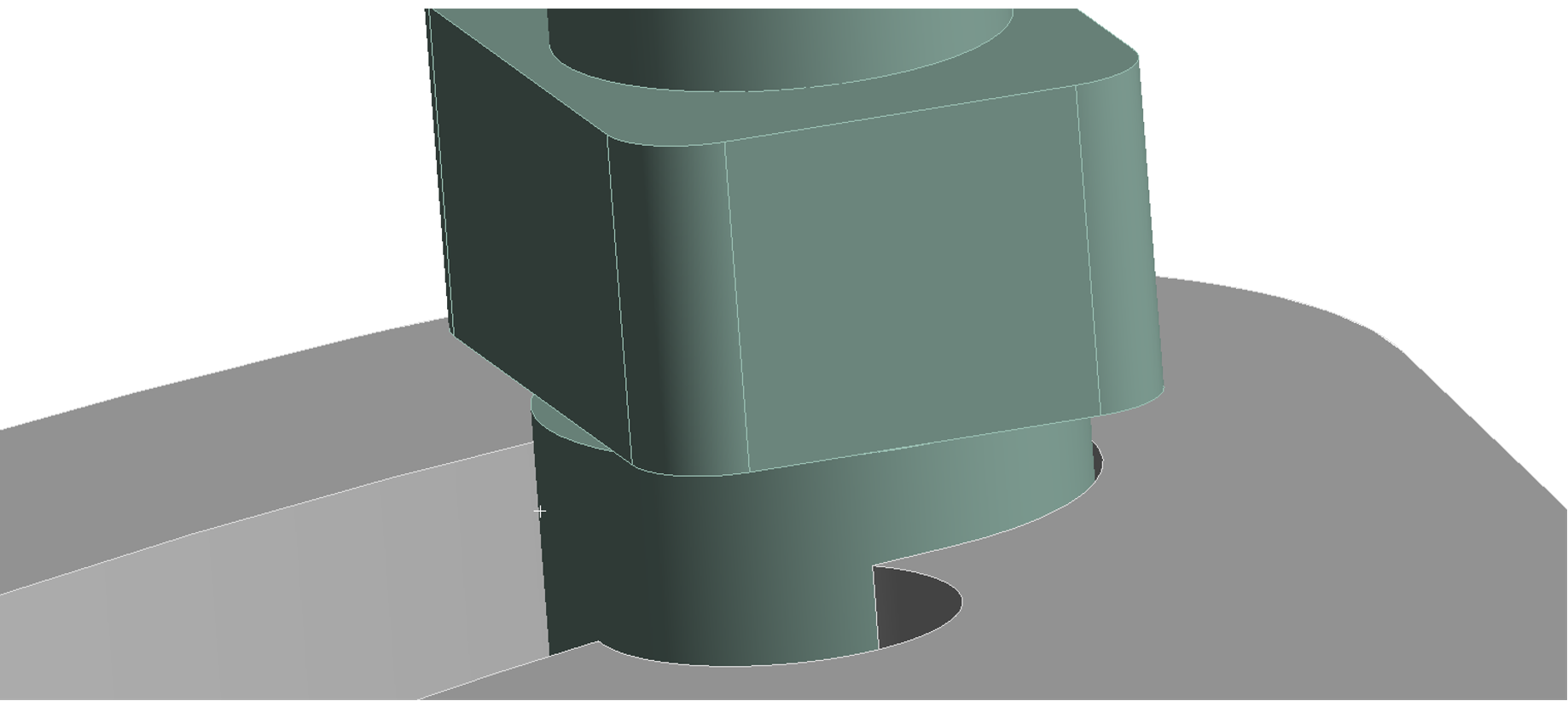
SubscriberI have a non-linear contact between the faces of two bodies, as shown below.
December 25, 2021 at 5:27 pmRameez_ul_Haq
Subscriber,would be delighted to hear your views on this issue, sir.
December 25, 2021 at 6:51 pmpeteroznewman
SubscriberI have worked with nonlinear models for about 10 years without needing to pay attention to the magnitude of the numbers in the NR residual plots or force convergence plots.
I have successfully resolved hundreds of convergence problems without knowing why the value of a residual was high relative to the applied load.
I paid attention to what had to be done to resolve the convergence failure and get to a fully converged solution, when that was possible.
In the images of the NR plots, I can tell that the elements are too large and the contact stiffness too large.
I would first try to soften the contact, which will allow more nodes on the large elements to share the contact load, at the cost of larger penetration.
If that fixes the convergence error with acceptable penetration, declare success.
If softened contact doesn't fix the convergence error, or the penetration when it does is unacceptable, I would try smaller, better shaped elements, and not so much reduction in contact stiffness.
December 25, 2021 at 7:07 pmRameez_ul_Haq
Subscriberthank you for the answer, sir.
I would first try to soften the contact, which will allow more nodes on the large elements to share the contact load, at the cost of larger penetration.
So both of these actions need to be done in conjunction, right? I mean if I decrease the stiffness, then I also need to increase the penetration tolerance, right? It wouldn't make sense to do one without the other, right?
December 25, 2021 at 7:27 pmpeteroznewman
SubscriberI leave Penetration Tolerance at Program Controlled and set the Normal Stiffness to Factor, then see if a value of 0.1 converges. If not, try a value of 0.01. These actions seem to have the desired effect without having to change the Penetration Tolerance.
December 25, 2021 at 7:41 pmRameez_ul_Haq
Subscriber,I understand. And even when these won't work, then we should be going for modifying the penetration tolerance then. Makes sense, sir.
Secondly, I would like to pitch in one more thing here. Imagine I have a contact (like the one I showed above) and just keep interface treatment as 'Add offset, No Ramping'. Now, there is an initial gap between the faces where the non-linear contact was built. When they come into contact during the analysis, then the structure doesn't have any rigid body motion but if they don't, then the structure will. For a frictionless contact, even when I set it to 'Adjust to Touch', sometimes I experience a Rigid Body motion error and the analysis doesn't even begin, but for the same faces but the contact now changed to frictional or rough, the Rigid Body motion error doesn't mostly occur and the analysis atleast begin. I don't know why, though. It appears like because the solver somehow figures out that when (during the analysis) the faces come into contact, then due to friction, the Rigid Body motion could be avoided. This is my understanding. If this is true, then how would the solver proceed? I mean since it has already started, how will it know that the frictional force would be enough between the faces of separate bodies which will avoid any rigid body motion. Would love to hear your views on this.
I am asking this because I feel like (since the solver doesn't give me a rigid body motion intially and just begins for this frictional contact), then it might not converge even for the smallest of loads initially because of rigid body motion happening within my structure. That is why the NR Residual forces are very high; maybe it has some relation to rigid body motion. What would you say?
December 25, 2021 at 8:37 pmpeteroznewman
SubscriberIf failure to converge is caused by contact stiffness being too high, there is very little penetration. So when you soften the contact stiffness by a factor of 0.1, that may bring it to an appropriate level of stiffness where the penetration, while being slightly more, is still a long way from the allowable limit set in the penetration tolerance setting. That is why you don't need to modify both at the same time.
In a Static Structural analysis, the solver will give a rigid body motion error when there is zero stiffness in any of the six DOF. In the two parts you show above, when the contact is closed with the force pushing them together and the contact has friction, a reaction force is created in all six DOF. If the friction is set to 0 (or changed to frictionless), there is zero force in the axial direction and that causes a rigid body motion error. A frictional contact that is open has zero force in all six DOF which causes a rigid body motion error.
One possible source of "hot spots" in the NR Residual Plot is large elements wrapping around cylindrical surfaces. While the nodes will lie on the cylindrical surface, the faces of the elements will deviate slightly from the cylindrical surface. Therefore, some nodes may have a higher amount of penetration and therefore contact force than other nodes due to the deviation of the target element face from the cylinder. As the elements get smaller, so does the deviation of the target element face from the cylinder.
December 25, 2021 at 8:53 pmRameez_ul_Haq
Subscriber,well yes, seems logical in what you said in your last paragraph. That could be a possibility.
A frictional contact that is open has zero force in all six DOF which causes a rigid body motion error.
Think of a near open contact (i.e. the frictional contact is tracked during the solution, but is open initially). Now, initially, since the contact is not closed, should I be expecting a Rigid Body error or not? What I have seen is that I don't experience any Rigid Body error even when the contact is near open for frictional contact. However, for the frictionless contacts, I usually do.
December 25, 2021 at 10:52 pmpeteroznewman
Subscriber,In the case of the green and gray parts, if the green part has no other connection to ground other than the frictional contact, then the contact must be closed for the solver to start. If the contact is near open, the solver will issue a rigid body error, unless weak springs are used.
December 26, 2021 at 4:30 pmRameez_ul_Haq
Subscriber,I just came across a video by Ansys Learning on YouTube, which addresses the issue I said in my previous comment.
This makes me feel like the intial force unconvergence that I was facing, and observing the high NR-Residual forces, might be solved by decreasing the number of load steps, instead of increasing them. This means that if the small load step is causing unconvergence due to no contact stiffness initially (and basically causing a Rigid Body motion), then increasing the initial load might turn the contact from open to closed and might not cause that unconvergence issue. Just a thought.
Ofcourse, as cited in the shared video, contact stabilization is also an option. But choosing an appropriate value for it still is an art I guess, and I don't know how to properly choose it.
You suggested about using weak springs to overcome the Rigid Body motion error. I guess that can be used when the solver doesn't even begin and issues an error for Rigid Body motion, but if the solver begins and force unconvergence problems arise (which is related to the Rigid body motion, essentially) due to contact status, then using contact stabilization damping would be handy. What are you views?
December 26, 2021 at 6:35 pmpeteroznewman
SubscriberThat's a great video. Ansys is frequently adding functionality that makes it faster and easier to take geometry and get a result with a minimum amount of effort. I learned to make contact models before Contact Stabilization was available in Mechanical, so I had to move parts in CAD prior to starting the model to get closed contact status. That works when the load is in one direction only, but doubles the work when the load reverses. Contact stabilization could potentially allow load in both directions to solve with no intervention.
I wanted to add another reason for "hot spots" in the NR residual force plot, which is the way a uniform pressure is resolved into nodal forces on quadratic elements. In the example below, a uniform pressure load of 120 Pa is on the top, a displacement of Y=0 is on the bottom of the square, and X=0 on the left edge.
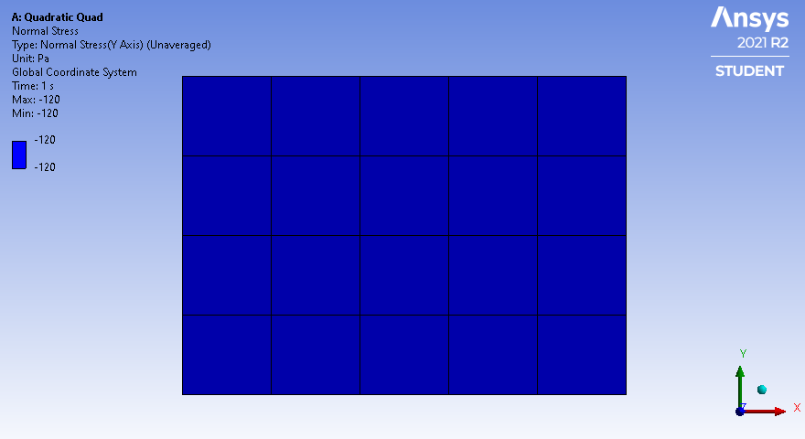
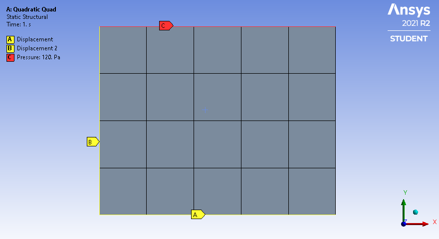 The element result is a uniform stress in the part. The reaction force on the bottom edge is 6 N. Note that along the bottom edge, there are three middle elements and two side elements.
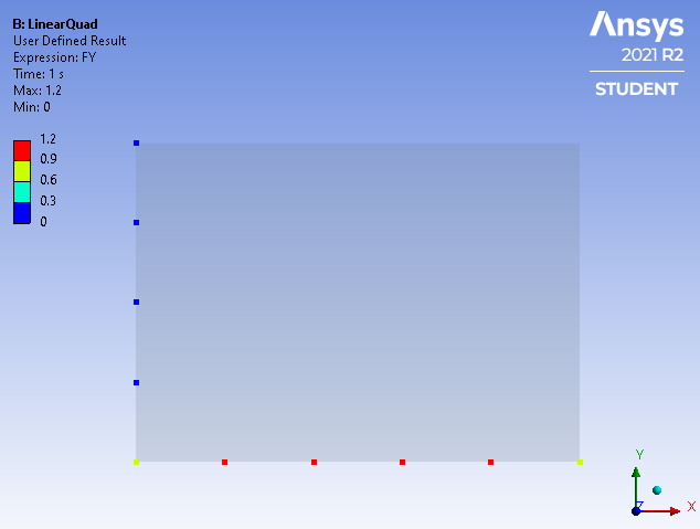
 For Linear elements, the nodal forces on the 4 nodes of the three middle elements is 1.2 N, while the corner nodes on the side elements have 0.6 N. It makes sense that the corner nodes on the side elements have half the nodal force since if another column of elements were added to that side, that node would be attached to two middle elements and the total nodal force would come up to the 1.2 N value expected on middle element nodes.
 For Quadratic elements, each element has a midside node and a corner node. The nodal force on the midside nodes of the three middle elements is 0.8N while the corner node on those middle elements is only 0.4 N. This means that for a uniform pressure, the nodal force oscillates high-low across each element face by a factor of 2:1 which is very different to the Linear elements where the nodal forces are constant across the middle elements. Similar to the Linear case, the side elements have corner nodes half that of a middle node at 0.2 N.
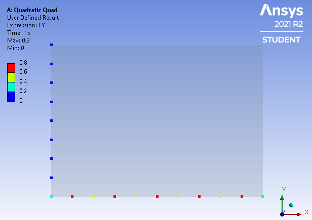 The above examples are for 2D elements, but the effect is even larger on 3D elements. See this reference:
http://rickbradford.co.uk/NodalForcesEquivalenttoPressure.pdf where the ratio in the middle of the face is 2:-1 which means the element corner nodal force is in the opposite direction to the pressure! See that the nodal force oscillates between -0.4 N and 0.8 N on the bottom face.
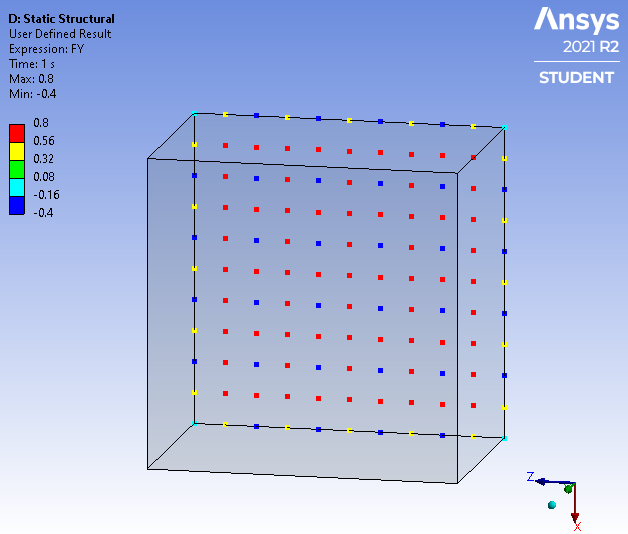 This same effect happens during contact. If the contact result is supposed to be a uniform pressure, the nodal forces are going to oscillate if you have quadratic elements. This is why in challenging contact problems, linear elements sometimes help, but due to the reduction in the ability to represent stress gradients, the element size should be cut at least in half to maintain the total number of nodes on the surface.
The problem is linear tetrahedral elements are to be avoided always because they are overly stiff, while linear hex elements are acceptable. However, it is a lot more work to create hex elements on complex geometry. A significant problem with linear elements is on cylindrical faces because linear elements have straight edges. Contrast that with quadratic elements that have curved edges. This means that if the nodes on the ID of the hole don't line up with the nodes on the OD of the post, but land in the middle of the element face, then there can be a significant deviation from the cylindrical surface.
December 26, 2021 at 7:55 pmRameez_ul_Haq
SubscriberThat works when the load is in one direction only, but doubles the work when the load reverses.
Exactly. That is what I was thinking. I mean even when the parts touch each other and there is no gap between the parts, then it is just gonna work in the direction of contact stiffness, without giving any Rigid Body motion errors or convergence problems. What if the load is in the other direction, and the contact stiffness in that direction is zero. Then it may straight away give a Rigid Body motion error, or cause covergence problems. I guess the Contact Stabilization Damping automatically deals with that. Thats a great service provided by ANSYS, and I appreciate that.
And thankyou for inserting a comprehesive example here, was helpful sir.
If the contact result is supposed to be a uniform pressure, the nodal forces are going to oscillate if you have quadratic elements.
Does this mean that faces coming into contact with each other will have variable stress along the face, and not a constant value of stress?
December 26, 2021 at 8:35 pmRameez_ul_Haq
SubscriberAnd can also provide some information on what is 'Elastic Slip Tolerance' and 'Update Stiffness' under the contact settings? What does it mean and when should this be used?
December 26, 2021 at 9:12 pmpeteroznewman
SubscriberIn 3D, that alternating pattern of +2,-1 nodal forces applied to the quadratic elements creates a perfectly uniform stress on the face of a solid body.
By contrast, linear elements have constant values of nodal forces on the face of a solid mesh to produce perfectly uniform stress.
The NR Residual plot shows Force imbalance. Maybe it is easier to achieve that balance with linear elements than quadratic elements.
December 27, 2021 at 8:00 amRameez_ul_Haq
Subscriber,so the stress figure that you shared for quadratic quad shows uniform stress along the whole length, which agrees with your statement that:
In 3D, that alternating pattern of +2,-1 nodal forces applied to the quadratic elements creates a perfectly uniform stress on the face of a solid body.
You didn't share the figure for the stress pattern for linear quad element, but I am guessing that would be the same (i.e. uniform stress) as you have already shared for the quadratic quad element. This makes me believe that the local force transfer could be different from node to node (like it could be different in quadratic element type from contact face to target face) but the stress is still going to be uniform, while the force transfer from node to node in linear element type would be uniform and the stresses will also be uniform. Apparently, it doesn't make a difference for the stress transfer occurring.
It raises a question that if I am not seeing any different stress contours in Quadratic order and Linear order, then why do I even need use the Quadratic order at all for the shell elements.
December 27, 2021 at 12:43 pmpeteroznewman
SubscriberHere are the nodal forces for a uniform pressure (and stress) using linear elements. All the nodes in the face not on the edge have a uniform nodal force of 1.2 N.
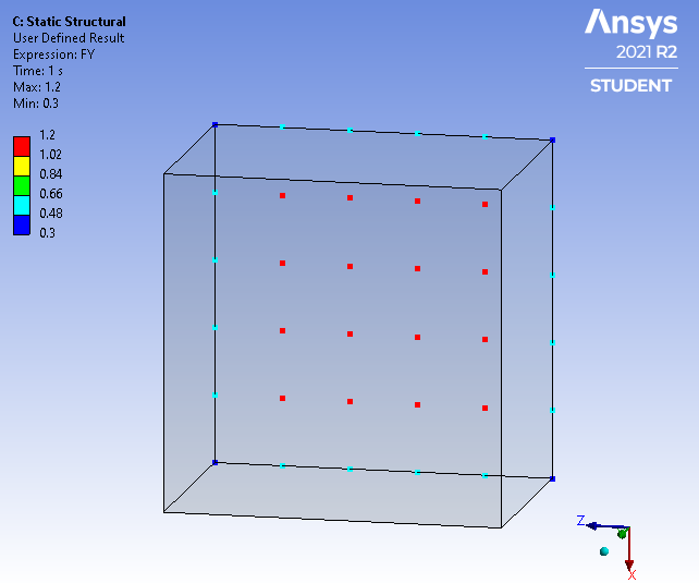 You use Quadratic elements because most problems don't have a uniform pressure and constant stress, but have stress gradients. Quadratic elements can represent rapidly changing stress more accurately than linear elements. Reducing the element edge length by a factor of 2 does not catch linear elements up to the fidelity of quadratic elements because two straight lines cannot follow changing stress as well as a parabolic curve.
December 27, 2021 at 1:17 pmRameez_ul_Haq
Subscriber,so at the start, I don't know that if the contact pressure (and hence the stress transfer) is going to be uniform or will have a stress gradient. If they are of uniform nature and I choose quadratic order, then the nodal forces will oscillate (which can cause some convergence issues) but the contact pressure (stress transfer) will still be uniform. Linear order elements are better suited in this case, at the contact locations.
If the stress is not of uniform nature but is actually expected to show stress gradients, then I should be opting for quadratic order because, as you mentioned, these can more accurately capture the stress gradient at the contact than the linear elements. So it basically all depends on what is expected to happen at the contact region, which can be checked by conducting an initial analysis.
Can you kindly tell me that if I go for linear elements and I am trying to capture the stress gradient at the contact, then the nodal forces (at the contact region) of elements won't be uniform any more, right?
And also, I just want to make sure what you said in your last paragraph. So according to my understanding, even if I replace a single quad order element with two linear order elements, then the stress can be changing only linearly in those elements, but for quad elements, the stress would be changing parabolically. Right? I don't know why it is assumed that parabolic change is more accurate then linear change, maybe it is because of the experience and experiments already conducted by people all over the world, which ensures parabolic change is more accurate.
Plus, if the displacements are changing linearly or parabolically in an element, then strains and stresses should change by the same degree, right? They cannot have a difference in the degree of change between them, right?
December 27, 2021 at 2:15 pmpeteroznewman
SubscriberThe stress in two linear elements (orange) varies by location compared with the stress in a single parabolic element (blue). The gap between the curves represents the error in the linear element compared with the parabolic element. Yes, as stresses change, so go the strains.
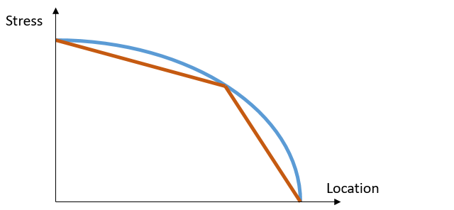 Yes, if the stress or pressure is non-uniform at the contact region, then the nodal forces will be non-uniform also, even though linear elements are used. It will just behave in a more predictable way.
It is possible for ANSYS to create new quadratic element types that have uniform nodal contact forces. Such elements are described in this PhD thesis: https://www.diva-portal.org/smash/get/diva2:999668/FULLTEXT01.pdf
December 27, 2021 at 3:06 pmRameez_ul_Haq
Subscriber,perfect, sir. Thank you for this.
Just one more thing; can you also provide some views on this comment I made yesterday:
And can also provide some information on what is 'Elastic Slip Tolerance' and 'Update Stiffness' under the contact settings? What does it mean and when should this be used?
And what you said about decreasing the contact normal stiffness and then again conducting the analysis, well IT WORKED. Thank you for that, sir. But I want to know that how does it work? What is the role of normal stiffness in making the contact to overcome convergence problems? I mean decreasing stiffness means that penetration automatically increases (but still less than the tolerance), however the overall contact force remains same. So how can it help in convergence?
Plus, what are the drawbacks of playing with it so that convergence is achieved?
December 27, 2021 at 5:00 pmpeteroznewman
SubscriberThis is the page in the ANSYS Help system that describes Update Stiffness: Advanced Settings (ansys.com)
I don't know what Elastic Slip Tolerance is or what it controls. I have never changed the default value.
Softened contact (0.1 Normal Stiffness Factor) helps resolve non-convergence because it allows more nodes to share the contact load. Instead of a few nodes with high nodal forces causing high stress gradients within a single element, many elements can have all the nodes in the contacting face have some nodal force, reducing the NR Force Residual.
December 27, 2021 at 6:01 pmRameez_ul_Haq
Subscriber,so basically having a localized high value of force in a contact (due to high contact stiffness) can cause convergence issues because the elements' internal forces cannot find equilibrium with the high localized contact forces, which can result in high NR Residuals? Is that statement correct, sir?
December 27, 2021 at 8:09 pmpeteroznewman
SubscriberYes, that is correct.
December 28, 2021 at 11:50 ampeteroznewman
SubscriberA useful tool to eliminate pressure distribution defects is to go back to SpaceClaim (or DesignModeler) and Imprint the surfaces.
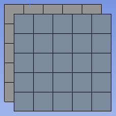
Without Imprint
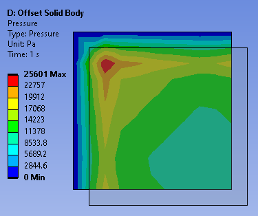
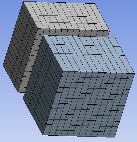
Take the case of two blocks that are slightly offset and have frictional contact between them. The corner nodes line up with midside nodes. This has a bad effect on the pressure distribution due to what was shown above with the corner node to midside node variation.
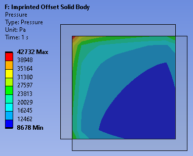
 The pressure distribution below shows a hot spot on the corner node of the bottom block and the high stress is along the other corner nodes. This is wrong.
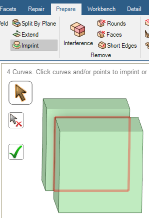
 With Imprint
In SpaceClaim, use the Imprint tool.
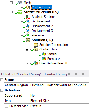
 In Mechanical, use the Contact Sizing Mesh Control.
 Now Corner Nodes line up with corner nodes and midside nodes line up with midside side nodes.
 The pressure distribution is now more sensible. The highest pressure is at the corner and along the edges.
December 28, 2021 at 7:35 pmRameez_ul_Haq
Subscriber,well thankyou again for this illustration.
I am going to ask one more thing here, sir. Imgaine I keep on using the detection method for a frictional contact as program controlled, which is basically integration points, now we know that the target surface cannot penetrate through the contact surfaces as soon as these integration points detect the presence of target surface onto it. But my question is that still the force transfer (from contact to target, for example) would be occurring from node to node, right? It doesn't matter what detection point I choose, the force transfer is bound to occur at the nodal locations, am I correct sir?
December 28, 2021 at 9:40 pmpeteroznewman
SubscriberYes, the contact force has to go through the nodes.
December 29, 2021 at 8:04 amRameez_ul_Haq
Subscriberthankyou for confirmtion.
Can you kindly tell me when should the 'Contact sizing mesh control' be used?
December 29, 2021 at 1:26 pmpeteroznewman
SubscriberWhen accurate pressure distribution is of interest.
When using quadratic order elements.
When the contact will only see small sliding.
When having convergence difficulties.
December 30, 2021 at 7:36 amRameez_ul_Haq
Subscriber,you wrote something on this thread which goes as Yes, if the stress or pressure is non-uniform at the contact region, then the nodal forces will be non-uniform also, even though linear elements are used. It will just behave in a more predictable way.
Imagine a linear element in contact where, as you said, that the nodal forces of an element in contact can be non-uniform because the stress/pressure distribution at that contact is supposed to be non-uniform. Now, the element still needs to be in equilibrium, right? So if the nodal forces of a linear order element are non-uniform, then how does the element maintain equilibrium?
December 30, 2021 at 6:13 pmpeteroznewman
SubscriberA nonlinear pressure profile gets linearized by the linear elements supporting that pressure. Linear hex elements have four nodes on the face supporting the pressure. Those four nodes can take on any nodal force value that results in equilibrium.
December 31, 2021 at 2:20 pmRameez_ul_Haq
Subscriber,absolutely true. Thankyou again.
One more thing I would like to ask here sir, was I right when I said that a parabolic approximation (using a quadratic order type) for displacements, strains and stresses represents the reality more closely than a linear approximation? Or it depends on various other factors like boundary conditions, loading conditions, etc?
December 31, 2021 at 5:23 pmpeteroznewman
SubscriberQuadratic order elements are generally the better choice for accurate stress and are therefore the default element in Static Structural.
Linear elements are required if using the Explicit Dynamics solver.
Linear elements might help in Static Structural models with contact when other methods of obtaining convergence have failed.
March 2, 2022 at 9:28 pmRameez_ul_Haq
Subscriber,welcome back to this thread. You mentioned about the nodal force varying pattern within elements that we observe for 3D solid elements and 2D shell elements, depending on whether they are of linear or quadratic element type. But you mentioned this pattern specifically for pressure (or in other words, normal forces) applied on the face of a 3D body or edge of a 2D body.
Should I be expecting the same pattern for the nodal forces within elements if, say, I have a force tangent to the face (for 3D body) or tangent to the edge (for 2D body)?
March 2, 2022 at 10:44 pmpeteroznewman
SubscriberYes. Same shape function is present.
April 1, 2022 at 4:09 pmRameez_ul_Haq
Subscriber,so we talked about how the force varies along the nodes of a linear order element and a quadratic order element, but still the stresses are observed to be uniform along the part irrespective of if linear or quadratic order was employed. This was a very surprising fact for me, to be honest.
Consider the following example, please.
BONDED CONTACT [Formulation = MPC] :

FIXED JOINT [Behavior = DEFORMABLE] :
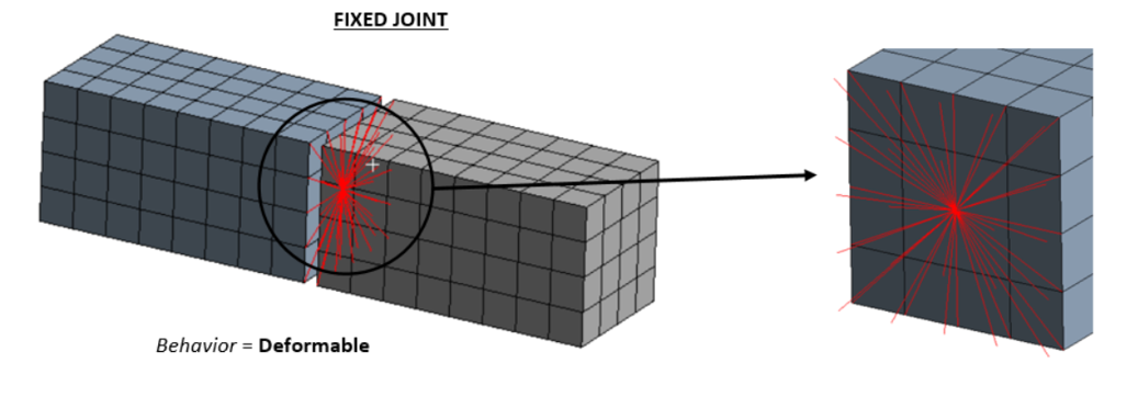 For the fixed joint, I am well aware that the force and moment transfer to all of the nodes will be affected by the 'weighting factor', but I don't know how would the force and moment transfer occur in the bonded contact? One way is to manually check the nodal forces on the faces which are bonded together, but just observing these nodal force results without having some pre-knowledge about it will be somewhat pointless.
Moreover, would you expect the stresses within the parts to be the same in both of these cases or not?
April 2, 2022 at 3:10 ampeteroznewman
SubscriberIn the image below are the tip end of three cantilever beams that have been sliced into two halves where the halves are connected by, left to right: a Deformable Fixed Joint, an MPC Bonded Contact and by Shared Topology. There is a 1 mm gap between the two halves of the cantilever except for the Shared Topology which is required to have zero gap.
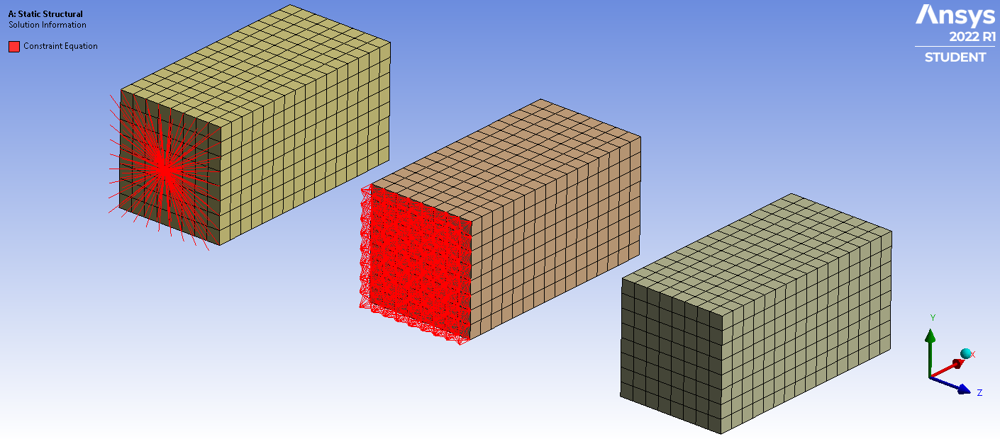
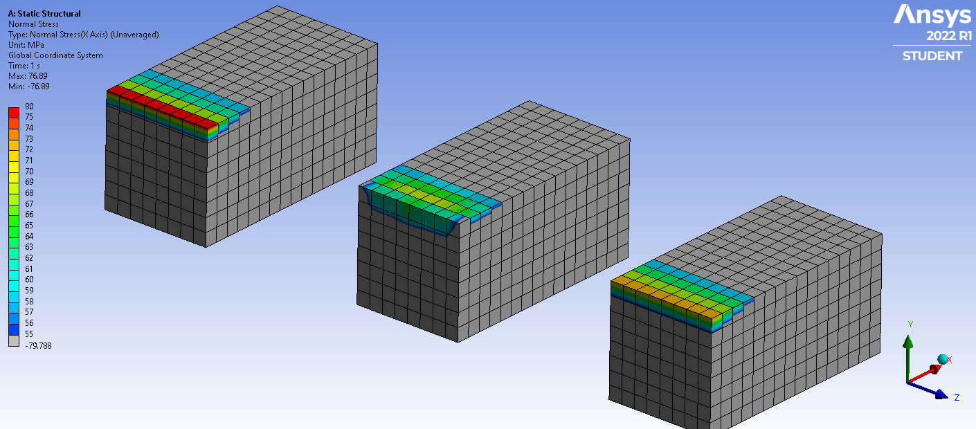 The shared topology value of stress is 72.6 MPa uniformly across the top edge. The Deformable Fixed Joint is higher at the top edge. The MPC Bonded Contact is lower at the top edge but rises one layer along X, which is the opposite to an analytical solution. It also falls off a lot at the corner. Both of these are artifacts from the spider of elements jumping a 1 mm gap, which is not ideal.
The best practice for Bonded Contact is to have no gap. If I open the geometry in SpaceClaim and move the hidden body face up to meet the visible end of the center beam like is done for the Shared Topology connection on the right, and reduce the Pinball radius to 0.001 mm, we get a node-to-node spider of MPC connection elements as shown below. This is ideal.
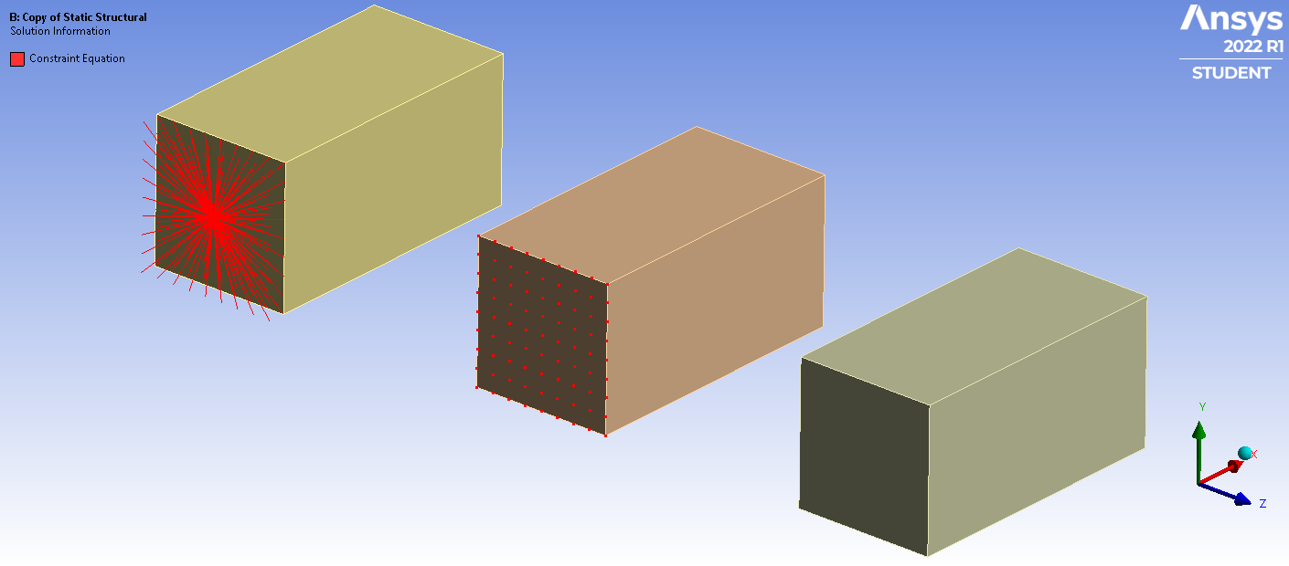
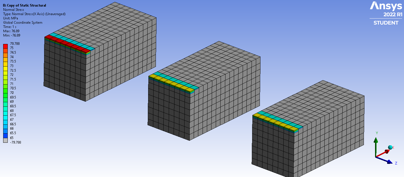 Now MPC Bonded Contact gives identical stress results to Shared Topology, which is the same as having a single body.
April 2, 2022 at 12:25 pmRameez_ul_Haq
Subscriber,so the results that I am seeing in the last picture that you shared for the FIXED JOINT case is also for when there is no gap between the faces of the two bodies? Or you still kept the distance of 1 mm between the two bodies for the FIXED JOINT case? I actually understood this that the gap of 1 mm is causing some artifacts for both, FIXED JOINT and BONDED (MPC) cases, but if I remove this gap and make the opposing faces of the two bodies to overlap each other, so the fixed joint would also give me the same results as I see for the BONDED (MPC) and Shared Topology, or not?
Secondly, you mentioned this:
Both of these are artifacts from the spider of elements jumping a 1 mm gap, which is not ideal.
Yes, it is not ideal since we are removing 1 mm length in between the two bodies which are being connected, but why is it causing an artifact (in stresses) is something which I would love to understand, because I don't know the reason for these artifacts to arise because of this gap.
You also said this:
reduce the Pinball radius to 0.001 mm, we get a node-to-node spider of MPC connection elements as shown below. This is ideal.
So increasing the pinball radius, to, say, 1.5 mm is not going to be ideal, even when we don't have any gaps between the faces which are being bonded together? Why is node-to-node ideal but node-to-several nodes not ideal?
April 2, 2022 at 1:38 pmpeteroznewman
SubscriberThe results for the Fixed Joint didn't change when I closed the gap and moved the Joint Coordinate system over to align with the split. It still has a different stress pattern than the node-to-node MPC and Shared Topology results.
When the MPC spider is connecting multiple nodes, it is adding stiffness to the region. This higher stiffness reduces the stress. That is not ideal.
When the MPC spider is node-to-node, it adds no stiffness to the region and so the stress is unaffected. That is ideal.
April 2, 2022 at 3:04 pmpeteroznewman
SubscriberNastran and Femap together provide an easy way to plot forces going through nodes. Femap calls it the Freebody tool. In the example below, I used a very coarse mesh so that it would be easy to see the forces on each node. There are only 2 linear elements across the depth of the beam, and three elements through the thickness of the beam, which is fixed on the left end and has a down force at the right end. Unaveraged Normal stress in the X direction is shown.
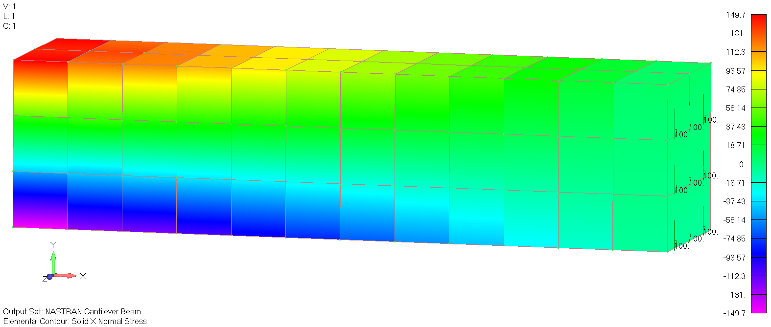 Here are the nodal forces in the X direction on a plane at the center.
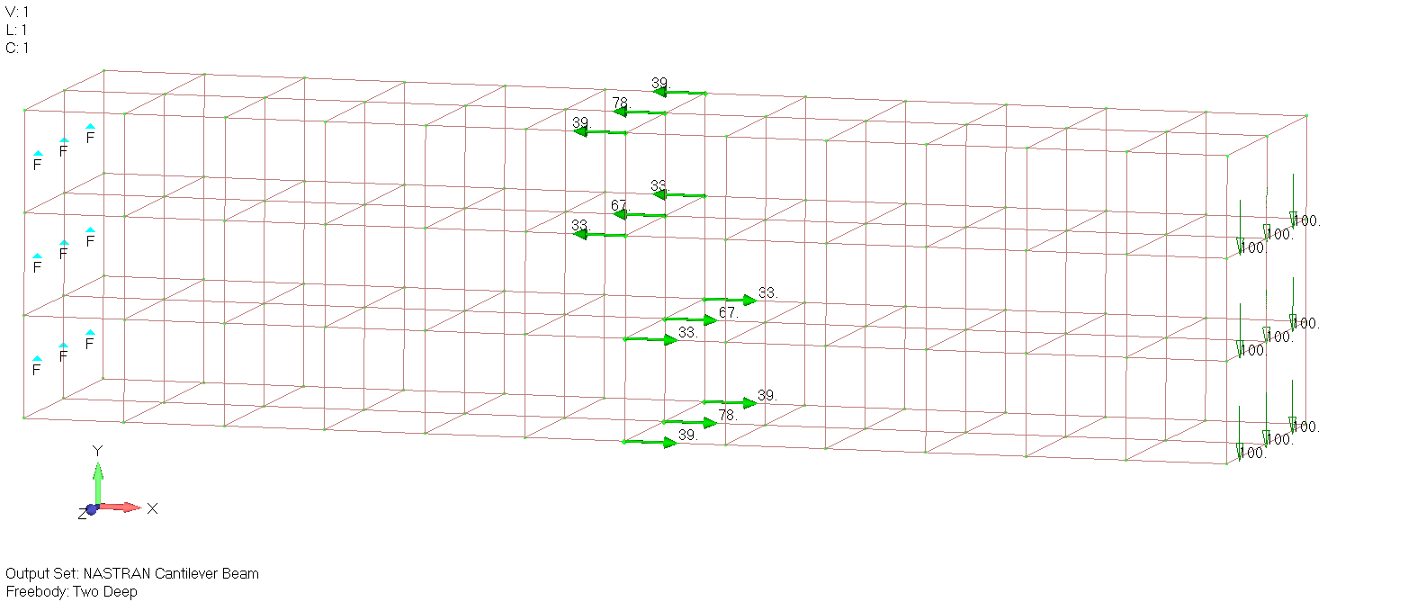 Here are the nodal forces in the Y direction, notice that the values add up to 100.
 I would like to figure out how to do this in ANSYS Workbench. Maybe Erik can advise.
April 2, 2022 at 4:11 pmRameez_ul_Haq
Subscriber,I have been trying to achieve in ANSYS what you have just shown in the pictures, but unfortunately I didn't find any luck. There are only two ways which I was able to discover in ANSYS: 1) creating a surface under constructing geometry and probing a force reaction on that surface to determine the total amount of load passing through that surface for a certain body 2) create an ENFO VECTOR user defined result, pick a Box volume of nodes whose total load I want to determine and then scope it to this user defined result. Unfortunately, both of these ways only inform me of the total amount of load passing through them (like the surface or the box volume which encloses a certain number of nodes within), but not node-by-node load, which you have shown in these pictures. I have to scope the user defined result i.e. ENFO VECTOR to each of the nodes separately in order to achieve what you have shown in the images.
Secondly, I sometimes become confused that why should we even care about the load that is getting transferred node-by-node at all [unless I want to know the total amount of load passing through a certain cross section within the body, like when I am trying to size the body]. Because, as you have shown already in this thread previously, the nodal forces can be different along the body (and they even depend on the order of element that I opt for), but the stresses are not effected by it. So why exactly are my stresses getting effected (or are different than those obtained by Bonded [MPC] or Shared Topology) when I employ a fixed joint to connect two faces of two separate bodies is something I couldn't get my head through it. Because I don't think fixed joint adds extra stiffness whatsoever when the behavior is set to deformable.
Viewing 38 reply threads- The topic ‘Why am I seeing Residual Forces so huge here?’ is closed to new replies.
Innovation SpaceTrending discussionsTop Contributors-
4989
-
1670
-
1386
-
1243
-
1021
Top Rated Tags© 2026 Copyright ANSYS, Inc. All rights reserved.
Ansys does not support the usage of unauthorized Ansys software. Please visit www.ansys.com to obtain an official distribution.
-
The Ansys Learning Forum is a public forum. You are prohibited from providing (i) information that is confidential to You, your employer, or any third party, (ii) Personal Data or individually identifiable health information, (iii) any information that is U.S. Government Classified, Controlled Unclassified Information, International Traffic in Arms Regulators (ITAR) or Export Administration Regulators (EAR) controlled or otherwise have been determined by the United States Government or by a foreign government to require protection against unauthorized disclosure for reasons of national security, or (iv) topics or information restricted by the People's Republic of China data protection and privacy laws.

