-
-
July 16, 2019 at 6:30 pm
nikos
SubscriberHello all,
I would like some help regarding an attempt at simulating the sloshing of a 3D tank which contains liquid.
I use ANSYS Fluent to model the fluid parts (VOF, explicit, 2 fluid bodies for water and air) and Transient Structural to model the tank structure (two bodies, lower and upper, so they can be assigned to the corresponding fluid bodies for Data Transfer in System Coupling solver).
Apart from the Standard Earth Gravity, I would like to know what support I need for the base of the tank, so it resembles a tank on the ground, that has also the the freedom to move under a sinusoidal acceleration, attempting to simulate an earthquake.
My guess is the elastic support but I had some issues running with it.
Thanks for any answer and any light shed on the matter.
Nikos
-
July 17, 2019 at 7:45 am
nikos
Subscriber -
July 17, 2019 at 11:10 am
peteroznewman
SubscriberThe problem with Elastic Support is it only provides stiffness in one direction, which causes numerical problems when the forces move the tank sideways.
You will have to put a cylinder of concrete and/or soil material, with a margin beyond the tank, to support the tank.Â
-
July 17, 2019 at 11:25 am
nikos
SubscriberThank you for your reply.
So what you are suggesting is that I make a base for the base of the tank and apply the elastic support on that?
Will it be essentially one more body underneath my tank with elastic support applied on it?
Should I also apply the sinusoidal acceleration on the new concrete/soil base cylinder?
Indeed, I need the tank to be able to move sideways.
-
July 17, 2019 at 3:06 pm
peteroznewman
SubscriberThe soil cut boundary (distant from the tank edge) would have a displacement BC that would have the XYZ displacement motion of the earthquake. The tank can sit on the soil and have frictional contact.
I recently worked with a 30 second earthquake record, sampled at 1,400 Hz so there were 42,000 rows of data in the 30 second time history, with 3 coordinates for a total of 126,000 numbers in the input data. I had to play some tricks to avoid bringing Mechanical to its knees.
If you just want sinusoidal motion, you can use an equation. How much time are you expecting to simulate? You will find that Transient Structural will rapidly fill up terabytes of space on your HDD.
-
July 23, 2019 at 6:12 pm
nikos
SubscriberAs you can see below I have created a base disk under the tank and have tried to apply a contact (under connections) so that ground and tank interact with a friction coefficient.
I have applied a Fixed Support on the lower surface of the "Ground" (not the one in contact with the tank).
The issue I have encountered, is that I cannot select Boundary Condition under Acceleration -> Base Excitation (Yes) -> Scope ->Boundary Condition.
-
July 24, 2019 at 6:29 am
nikos
Subscriber -
July 24, 2019 at 11:11 am
peteroznewman
SubscriberDon't use a Modal pre-analysis. Delete that link and let the Transient be a full transient.
Replace the Fixed Support with a Displacement. The displacement can be tabular time-history data or the equation that results after you perform a double integration of the acceleration equation.
-
July 31, 2019 at 6:46 am
nikos
SubscriberFirst of all, thank you petereoznewman for all your input.
Secondly, we have made some progress and managed to insert the erthquake as displacements.
The thing is that almost every time we run, we get the following two errors
1. "highly distorted elements error"
2. "Cortex received a fatal signal (SEGMENTATION VIOLATION)"
Any ideas on what might be causing these errors and how to solve them?
Thanks again.
Â
-
July 31, 2019 at 2:45 pm
peteroznewman
Subscriber1. Where is the distorted element? The corrective action depends on where it is. Taking smaller time steps might resolve this problem.
2. This sounds like a computer error. How much RAM is installed in your computer? How much memory does the solver need to solve incore? You can find this last piece of information by opening the Solver Output under the Solution Information folder.
-
August 1, 2019 at 9:25 am
nikos
SubscriberThank you peteroznewman.
However, please take a look at this:
New error appeared on the analysis run.
"Update-Dynamic-Mesh failed. Negative cell volume detected" time step is 0.002.
Â
ERROR
ZONES/MESH
END OF RUN
We have also tried meshing in structural.
Â
I have attached a wetrasnfer link to a .wbpz file from our analysis if you want to take a look at.
https://we.tl/t-aSQ3EIMxaw
Thank you for all your help.
Â
-
August 1, 2019 at 2:55 pm
peteroznewman
SubscriberNikos,
I won't be opening your model as it exceeds the capability of the Student license.
There are several posts on this site about negative cell volume errors in FSI problems.
Search for that term and read those posts. The first thing to try is a smaller time step.
Good luck.
Peter -
August 5, 2019 at 10:19 am
nikos
Subscriber
-
- The topic ‘
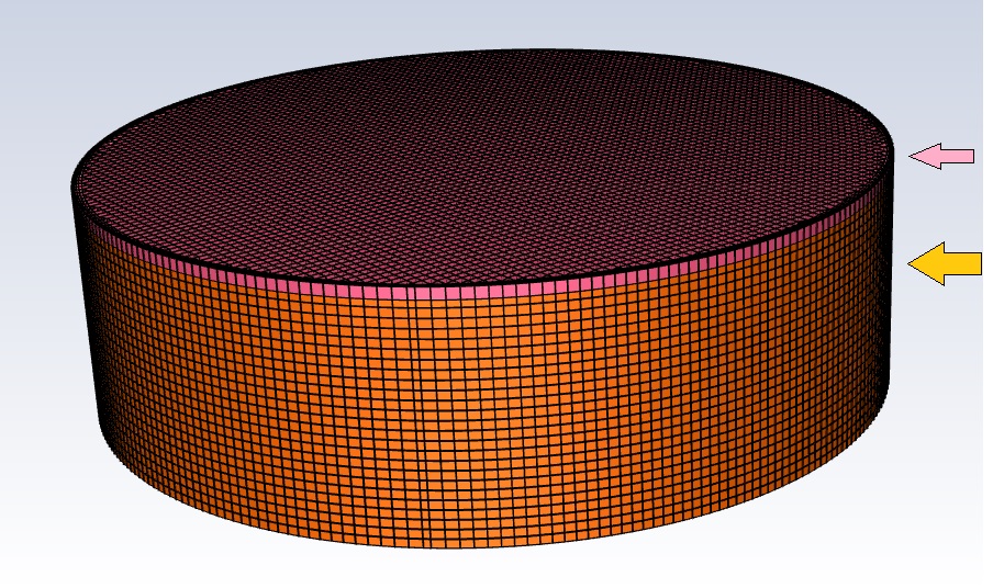
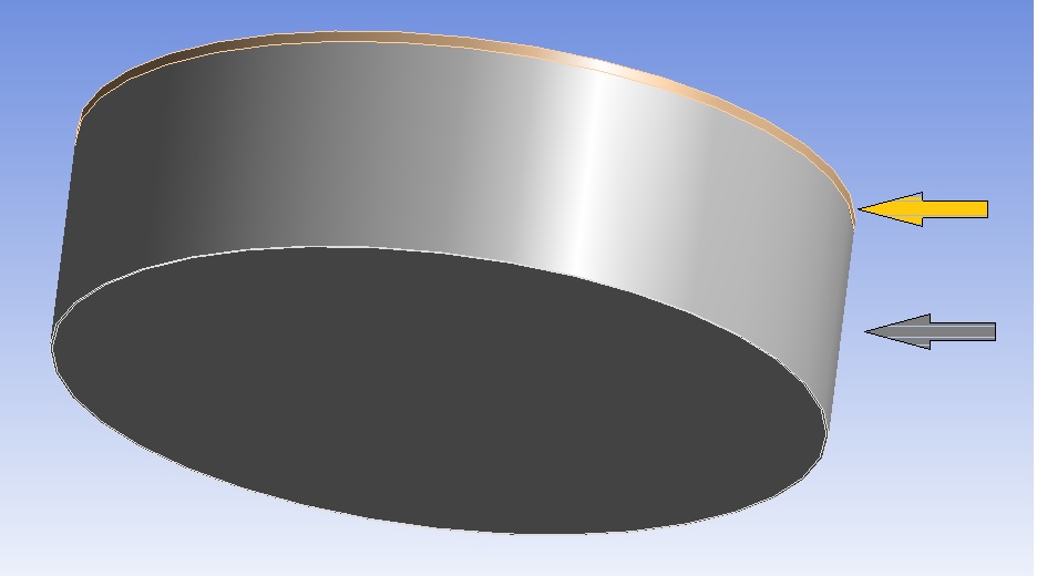
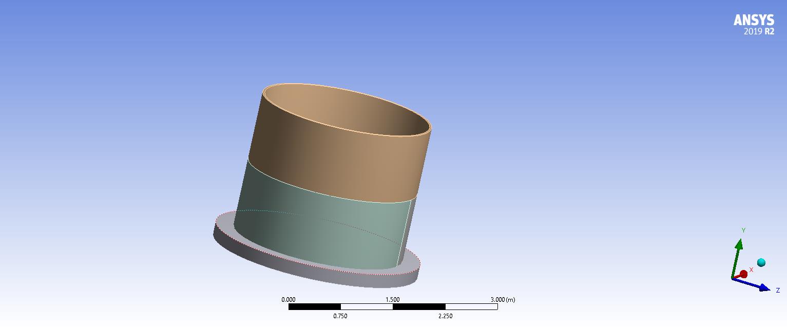
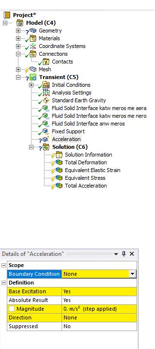
What support should be acting on base of tank in a 3D tank sloshing under earthquake.’ is closed to new replies.
- LPBF Simulation of dissimilar materials in ANSYS mechanical (Thermal Transient)
- Convergence error in modal analysis
- Simulate a fan on the end of shaft
- Nonlinear load cases combinations
- Real Life Example of a non-symmetric eigenvalue problem
- How can the results of Pressures and Motions for all elements be obtained?
- Contact stiffness too big
- Test post on Forum – LLM response – SC
- 13-Node Pyramid Element Shape Function
- Element Birth and Death
-
4482
-
1494
-
1376
-
1209
-
1021
© 2025 Copyright ANSYS, Inc. All rights reserved.


