

TAGGED: boundary-conditions, fluid-dynamics, meshing, modal-analysis, udf-fluent
-
-
October 14, 2021 at 2:53 am
Anadi_Mondal
SubscriberHello,
I am simulating air/water annular flow in the vertical tube using DPM and EWF models. But, I am getting negative film velocity after a small distance from the inlet. What might be the reasons for negative liquid film velocity?
1) Improper boundary condition?
2) Faulty mesh(ex. inappropriate first layer length near wall)
Or any other reasons?
Regards,
Anadi
October 14, 2021 at 9:18 pmSurya Deb
Ansys EmployeeHello,
You have not completely explained your model setup. Do you have gravity turned on? Do you use EWF for the water phase and how is DPM coming into picture?
Do you have DPM water droplets which get absorbed into the EWF?
What is the central core air velocity considering air to flow in the central core?
Regards SD
October 15, 2021 at 8:43 amSubscriberHello SD 1) I turned on the gravity and it's working in the negative z(axial) direction. I am using EWF for the water phase(liquid film at the wall) and DPM to simulate the core(air with droplets) of the tube.
2) Yes, if the water droplets touch the liquid film, it will be absorbed in the liquid film.
3) Central air velocity is high, about 42 m/s . Reynold's number for the vapor phase is about 103792.
I am using SST-K-Omega turbulence model with yPlus of 50(the first layer thickness near the wall is about 0.0002m). The mesh element has a length of 10mm in the axial direction.
If you need more info, please let me know.
Regards Anadi
October 17, 2021 at 6:58 pmSubscriber
Will you respond to my problem now or do you still need more info?
Anadi
October 18, 2021 at 3:10 pmRob
Forum ModeratorWe don't work weekends and depending on relative time zones you may find it takes a working day for someone to be online.
Check the near wall flow. How is the film added to the domain? What is the film thickness at that position? Also what is the mesh resolution like in the axial direction?
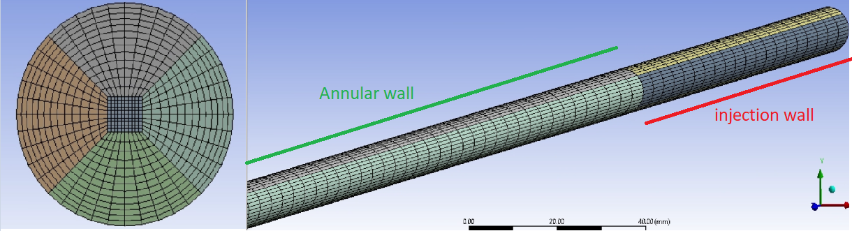
October 18, 2021 at 6:45 pmSubscriberHere is the cross-section of the mesh I am using(structured hexahedral mesh). For the air properties at 20┬░C and 4 bar( density 4.7604 kg/m3,viscosity 0.00001825 Pa.s) and yPlus of 50, the first layer thickness is 0.203026mm. The pipe diameter is 0.0094m, and I am using 13 divisions and a bias factor of 2 in the radial direction. The cell length in the axial direction is 10mm.
Case 1:
I have an injection wall in front of the annular wall to inject liquid mass flux using the EWF model. Vapor is entering at the inlet of the injection wall, and droplets from the injection and annular wall interface(DPM). I start droplets injection, entrainment with the starting of simulation(>=0.0s). So, the liquid mass flux at the injection wall, droplets flow, entrainment are working together with the start of the simulation. I use this logic to simulate steam/water annular flow earlier and I had no problem getting results.
Case 2:
I have an injection wall, stabilization wall, and finally the annular wall. Injection wall is used to inject liquid mass flux using EWF model, stabilization wall to stabilize the film and the annular section(main simulation part) where droplet deposition, entrainment happens. For this case, droplets start after 1.0 s of stimulation(allowed some time to stabilize film) and entrainment after 1.5s of simulation.
But for both cases, I got negative film velocity after a small distance from the inlet of the annular section. Obviously, I have a higher air velocity (18-72 m/s) here (air/water) than the steam velocity in the steam/water case(12.0352 m/s). Moreover, droplets diameter in air/water system(0.0000576m) is less than steam/water (0.0007m) system.
Another difference from the steam/water system is the source term. For the case of steam/water, vapor core and the liquid film were coupled with the source term( sink for liquid is the source for vapor). But in this case ( air/water) air has no source and sink term, and water has one sink term(entrainment). Is there any problem here?
Now, can you guess what might be the problem of negative film flow rate?
Regards Anadi
October 19, 2021 at 9:58 amForum ModeratorPlot the film thickness and flow velocity (node values off) in the region around the inlet. Most likely the film thickness is effectively zero and the flow is messy as it's right next to the inlet.
October 19, 2021 at 5:29 pmSubscriber
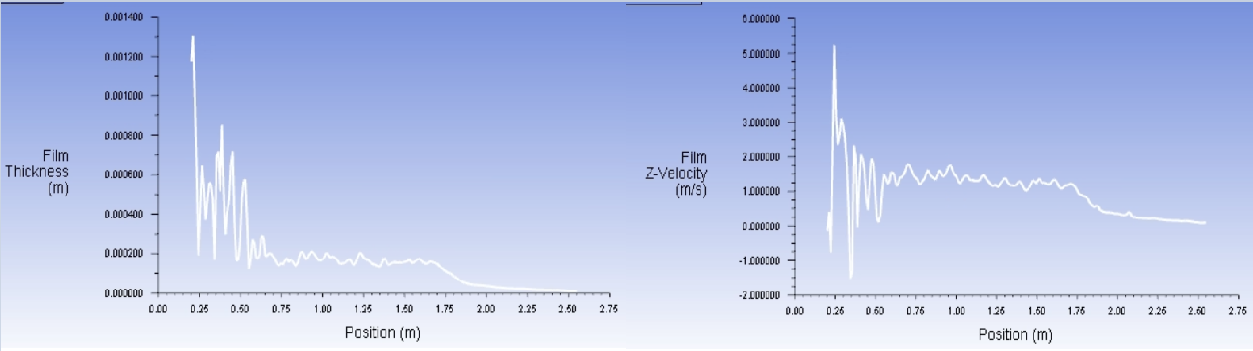
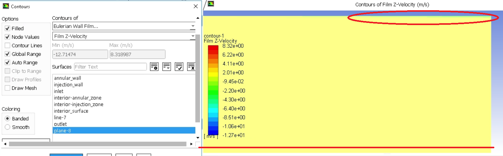
Here is the plot of film thickness and film velocity with node values after stimulation of 0.6792s . Here I start droplet injection, entrainment with the starting of simulation.
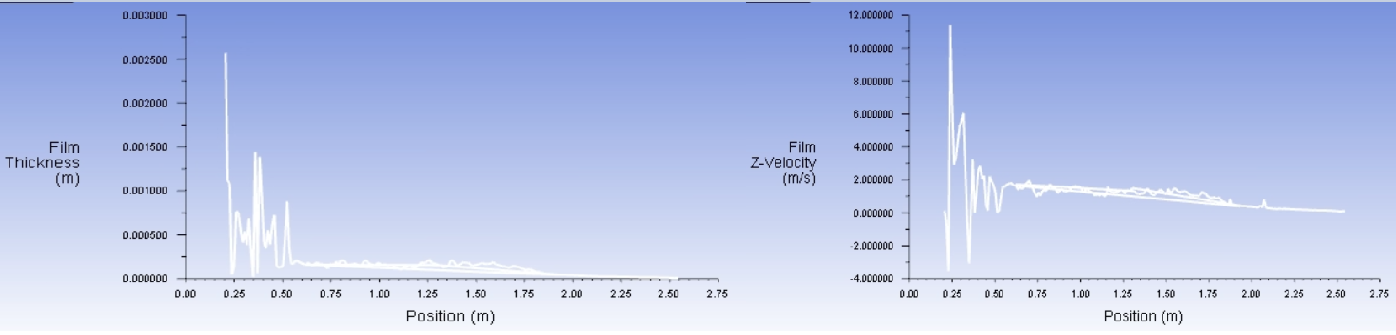
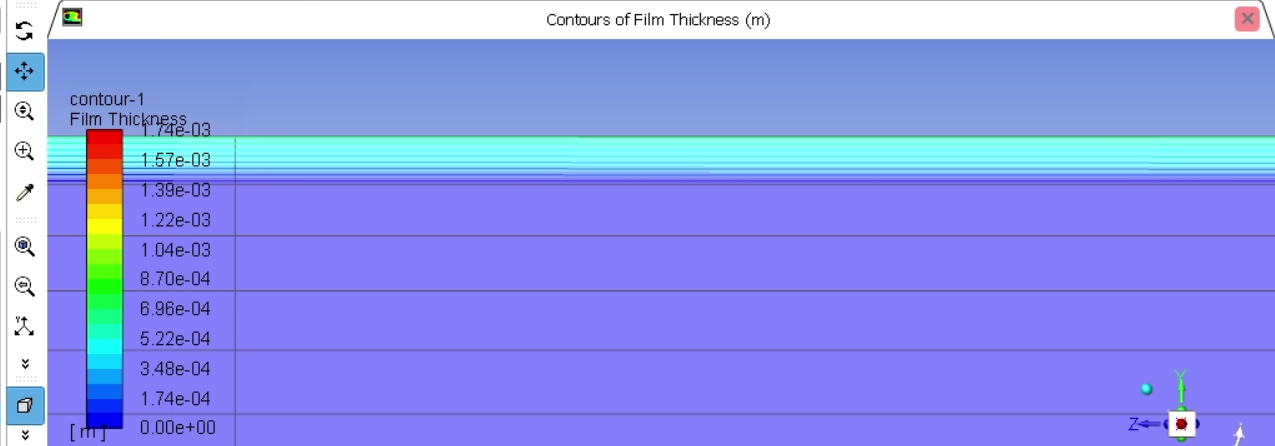
 Here is film thickness and velocity with node values off
 Now, which recommendation do you have for me? Do you have any suggestions for layer thickness near the wall, droplets diameter, mesh quality etc?
Regards Anadi
October 20, 2021 at 10:27 amForum ModeratorFirst cell height needs to be larger than the film for the physics to make sense: it's a thin film model. Re the above graphs, plot a contour of velocity across the channel and zoom in around the inlet. Think about what inlet condition you set, and how long it takes a flow profile to develop in a pipe.
October 20, 2021 at 3:53 pmSubscriber
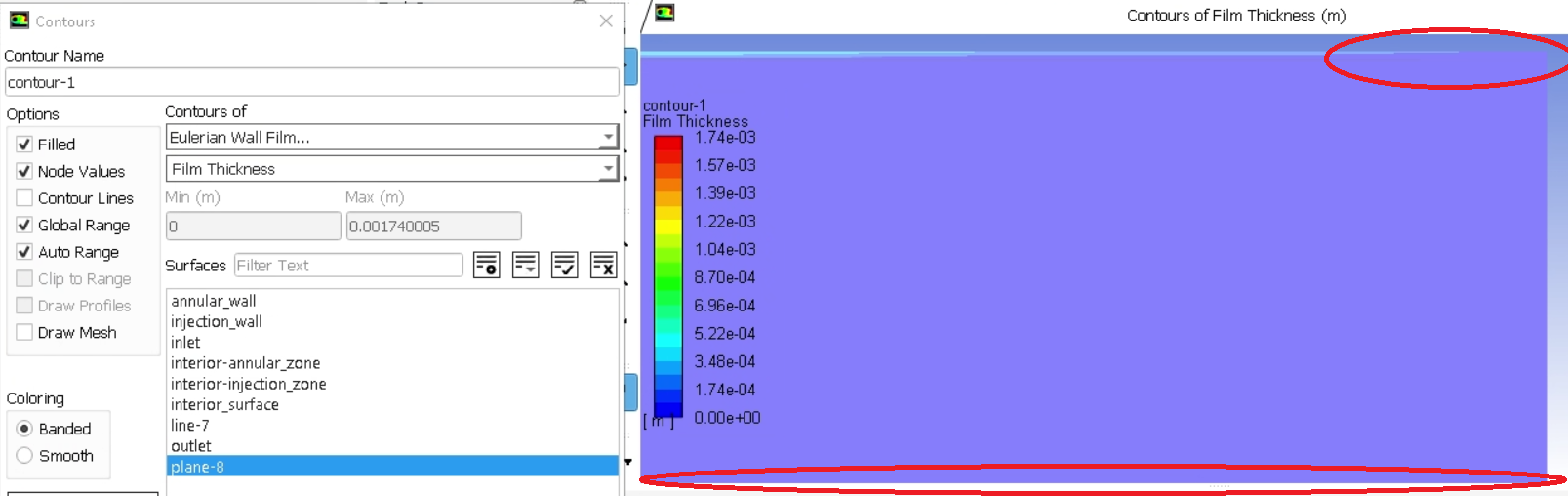
Okay, I am following your recommendation for first cell height. From the contour graph, I see that there is no film just after the inlet section. This might be the reason for abnormal/negative velocity just after the inlet. But one thing I notice is that film thickness and film velocity at the bottom and up of the pipe are different. As I am injecting liquid mass flux around the circumference uniformly using the EWF model, film thickness and velocity should be the same around the pipe. Is there any specific reason for happening these?
As the film thickness is disappearing at the inlet, should I simulate for a longer period? From the experimental result, I only know the liquid mass flow rate at the inlet.
Flim thickness contour-
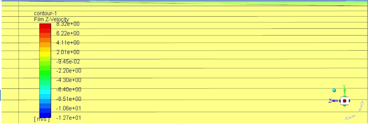
 Film Velocity:
 Regards
Anadi
Regards
Anadi
October 20, 2021 at 3:57 pmForum ModeratorFilm is up to 1mm thick with a 0.2mm near wall cell. That's not going to help as the film sees the near wall cell velocity. Now, if you look at the flow field, how does the z-velocity change over the first few cells and diameter?
October 20, 2021 at 5:31 pmSubscriber
From the earlier posted film thickness graph, the film is 1mm thick just at the inlet but it decreases sharply. It fluctuates between 0.8 to 0.2 mm for a little distance and for the rest of the length thickness is less than 0.2 mm. So if I select the first layer thickness 0.2mm, for the maximum distance the film would be within the first layer height(first layer cell height is larger than film thickness). Do I still need to increase the first layer height by more than 0.2mm to hold the film?
Based on the posted images and results, which changes I should make to skip these issues?
Here is the image:
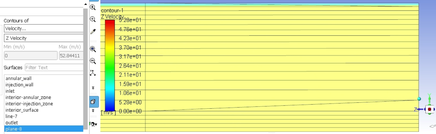
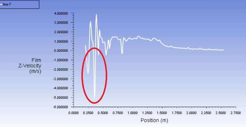
 Here is how velocity changes along z-direction:
 Regards
Anadi
Regards
Anadi
October 21, 2021 at 4:22 pmForum ModeratorWhat is the bulk FLOW velocity in that region? Not the film.
October 21, 2021 at 4:57 pmSubscriber
Here is the bulk velocity in that region:
 Regards
Anadi
Regards
Anadi
October 22, 2021 at 7:20 amSubscriber
Do you think the high velocity in the bulk region is responsible to make film thickness almost zero just after the inlet? Or is there any other reason responsible for negative film velocity? Moreover, I mentioned film thickness and first cell height in the earlier comment. Will you comment on it? Do I need to make any changes in any parameters, mesh quality in radial and axial directions or models?
Anadi
October 22, 2021 at 8:51 amForum ModeratorThink about how flow enters the domain. You assign a uniform velocity bc but the velocity at the wall is zero. As a result we expect some odd results next to a boundary: hence the recommendations about ensuring the interesting stuff isn't next to the boundary.
The film is than added into the domain from the wall with (I assume) zero momentum.
In the first layer or few of cells adjacent to the inlet the flow needs to adjust from the assigned value to the calculated value. You also have a very thin film with zero axial velocity that needs to accelerate to match the flow AND gravity.
The mesh looks OK-ish but you may want to increase the axial resolution while the solution is changing in that direction. The reason we don't always like high aspect ratio cells is because in EWF and multiphase the solution often changes along the cell.
Viewing 15 reply threads- The topic ‘What is the reason of negative film flow rate in annular flow?’ is closed to new replies.
Innovation Space Trending discussions
 Top Contributors
-
peteroznewman
 5824
5824 -
scabo
 1906
1906 -
Dennis Chen
 1420
1420 -
javat33489
 1305
1305 -
Shyam Prasad V Atri
1021
Top Rated Tags
© 2026 Copyright ANSYS, Inc. All rights reserved.
Ansys does not support the usage of unauthorized Ansys software. Please visit www.ansys.com to obtain an official distribution.
-


The Ansys Learning Forum is a public forum. You are prohibited from providing (i) information that is confidential to You, your employer, or any third party, (ii) Personal Data or individually identifiable health information, (iii) any information that is U.S. Government Classified, Controlled Unclassified Information, International Traffic in Arms Regulators (ITAR) or Export Administration Regulators (EAR) controlled or otherwise have been determined by the United States Government or by a foreign government to require protection against unauthorized disclosure for reasons of national security, or (iv) topics or information restricted by the People's Republic of China data protection and privacy laws.
