General Mechanical

General Mechanical

Topics related to Mechanical Enterprise, Motion, Additive Print and more.

What is the difference between bilinear and multilinear plasticity models?

    • yappyap
      Subscriber
      Hi all,nFrom what I know, bilinear plasticity model can be used to model linearly elastic perfectly plastic by inputting tangent modulus = 0 Pa. This means that the static structural simulation shouldnt go past yield point right?nWith multilinear plasticity model, does it mean that the original yield point has already been exceeded? I'm not too sure what multilinear means?nI have been tasked to validate my real-life experiments by using a material property that has not and would not exceed yield point but bilinear plasticity model does not seem to produce great results that multilinear does. However, i cannot justify the use of multilinear either as i do not understand its theory.nHope to hear from someone soon.nThank you (:n
    • peteroznewman
      Subscriber
      nOpen the ANSYS Help system, go to Mechanical APDL, Material Reference, Nonlinear Material Properties, 4.4 Rate-Independent Plasticity. There you can read more about these material models.nUsing a plasticity material model allows the simulation to compute the response of the structure to loads that take the material past the yield point. nBilinear means there are two straight lines, one is the elastic line, which is defined by Isotropic Elasticity, the other is the plastic line. You are correct that entering 0 for the Tangent modulus creates an Elastic-Perfectly Plastic material. This is often used because it is a conservative assumption.nMultilinear means there is more than one plastic line. It works much like the Bilinear model, but has the ability to follow a more complicated stress-strain curve. One item that makes using this a bit more difficult than Bilinear is that the Engineering Stress-Strain curve that is recorded when a material is tested in a Tensile Testing Machine is that the data has to be transformed to True Stress-True Strain before entering numbers in the Multilinear Plasticity material model.nIf you want to provide details about the material, geometry, supports and loads applied, we can look at the ANSYS model and the experimental data to help you validate your model.n
    • yappyap
      Subscriber
      Hi Array ,nSo when my professor mentioned that i should be comparing the simulation before it has reached the yield point, does it mean i can use multilinear too? if that's the case, how do i know which is the yield point if there's more than 1 plastic line? Or is that the reason why i have to use bilinear?nThe geometry is the brace shell from /forum/discussion/22814/stress-strain-curve-not-bilinear#latest , using linear mesh. My current input still remains as orthotropic due to my professor's decision. However, i recently came across this article that showed PA2200 is a quasi-isotropic material according to http:/utw10945.utweb.utexas.edu/sites/default/files/2015/2015-69-Faes.pdf , thus i may have to change the material properties? I was also wondering if ACP/Pre/Post works on quasi-isotropic PA2200 since it's not a composite material?.I currently have 2 supports at the spine of the brace: 1 fixed support on top and 1 displacement support where x and y are fixed but z is free, at the bottom (to prevent over constraints). nMy actual experiment looks like this: n
    • yappyap
      Subscriber
      Hi, sorry this is the current graph. The one i posted earlier was an outdated one. nn
    • peteroznewman
      Subscriber
      ArraynWhen your professor said compare the simulation before it has reached the yield point, it means you don't want any plasticity in the material model. Delete them from the material model.nUnder Analysis Settings, you must turn on Large Deflection.nChange the ANSYS supports to be more like the experiment. Delete the Fixed Support on top and the displacement support at the bottom.nCreate one Remote Displacement on the Fixed edge of the brace using the two points where the fixed hook is touching. Set X, Y, Z, and Rotation X and Rotation Y all to zero, leaving Rotation Z Free.nCreate another Remote Displacement on the Load edge of the brace using the two points where the load hook is touching. Set X = 200 mm, Y = 0, leaving all others free. This will stretch the brace exactly like it is being stretched by the apparatus.nUse a Probe on the Reaction Force of the Remote Displacement. What are the units of Force in the experimental data? nMake the End Time 200 s then each second equals 1 mm.nHow much does the brace weigh? Gravity is pulling down on the brace as it hangs from the hooks. When you put the first 500 g of tension on the cable, what is the angle of the cable relative to the tangent point on the pulley and the fixed point on the cable opposite it? As you put the second 500 g of tension on the cable, what is the new angle of the cable? This is a systematic error between the model and the experiment since the loads described above do not include these angles.nIn the experiment, how is the displacement measured? Is it the movement of the cable with the weight on it or is it a direct measurement of the distance between the edges of the brace? If you are measuring the movement of the end of the cable that has the weight on it, that is another systematic error between the experiment and the model since you are stretching not only the brace but also the cable. What is the stiffness of the cable?nWhy does the experimental data not start at (0,0)? You should zero out the displacement readout on the experiment before you overlay it on the simulation data but subtracting the initial value from all displacement readings.n
    • yappyap
      Subscriber
      thank you for your response.nThe brace weighs 615.5g. Should I turn on the Gravity option in Mechanical?n We recorded the angle during the experiment and the graph shown is the force resolved in the x-axis. nTo obtain the displacement, we measure the initial opening of the brace and measured the same opening once loaded. The difference is then taken to obtain the actual displacement, so yes it is the direct measurement of the distance between the edges of the brace:nThe experimental data does not start at (0,0) because we were using a pulley and a weight holder. Hence it starts from the weight holder's mass:nI hope this helps to clarify the experiment further (:n
    • yappyap
      Subscriber
      The unit of force in the experimental data is Newton (N).nI tried to Solve Mechanical according to your recommended BCs but there was this error:nn
    • peteroznewman
      Subscriber
      nI suggest you get four long pieces of string. Tie one piece to the loop at one end of the hook and another piece to the loop at the other end of the hook. Repeat for the other hook. Tie the other end of these four strings to the ceiling. Now you have supported the hooks with four long strings that attach to fixed points on the ceiling. Those four strings can support the weight of the brace and allow the fixed string and the tension spring to be horizontal with zero tension. The distance across the back of the brace when it is hanging from the ceiling with zero horizontal tension may be slightly larger than when the brace is supported on a tabletop, but call that value zero displacement. Now you can apply a pure horizontal force and measure the deformation from the hanging distance.nIs the simulation done with solid elements or shell elements? Two nodes are not good to scope for a Remote Displacement if the nodes are connected to solid elements, but might be acceptable for shell elements. In either case, add many more nodes to the scope for each Remote Displacement. That will spread the load. Make the Remote Displacement have a Deformable behavior.n
    • yappyap
      Subscriber
      nI will try the experiment again with your suggestions when i'm back at school.nThe simulation was done with shell elements. What does Deformable behavior mean?nCould I use Named Selections and select a couple of nodes for one selection, then probe the group of nodes through the Named Selection?n
    • peteroznewman
      Subscriber
      nAdd all the nodes along one edge between the two hook contact points into a Named Selection, then scope one Remote Displacement to that Named Selection. Repeat for the other edge.nDeformable means that it averages the force over many nodes without adding any stiffness. The other choice is Rigid which makes all those nodes move together, but that adds stiffness and creates high stress on the elements that have some nodes included in the Rigid group and some nodes outside that group.n
    • yappyap
      Subscriber
      thank you for your suggestions.nMay I ask if applying Shell 63 would help get better results for orthotropic materials? Also, i tried using the command ET, MATID, SHELLXXX but the Solution Information kept showing Shell181 for Linear and Shell281 for Quadratic. It seems that the command isn't applying?n
    • yappyap
      Subscriber
      ArraynI do not seem to have the option for Deformable behavior:n
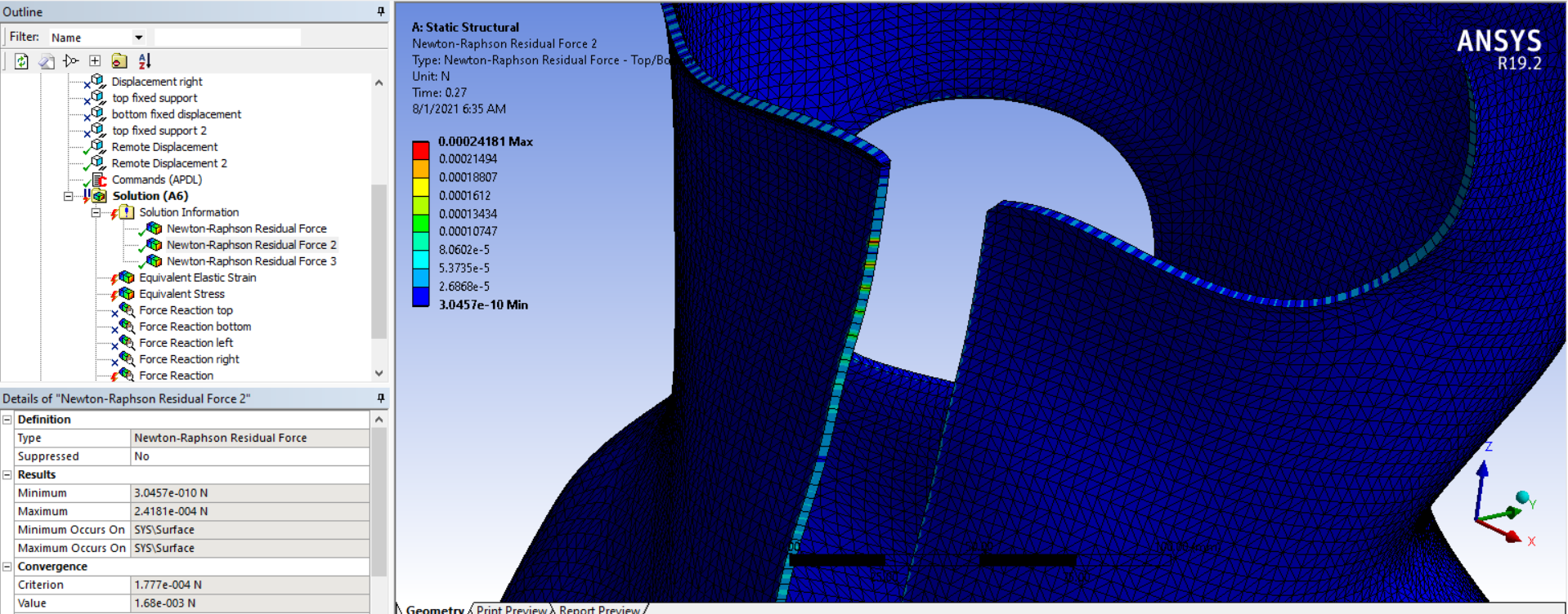
I'm using ANSYS 19.2n
    • yappyap
      Subscriber
      In addition, I am unable to select the Named Selections for the Remote Displacements if I use nodes. I previously used vertices and was able to select the Named Selections.nn
    • peteroznewman
      Subscriber
      nThere is no such element at SHELL63 in ANSYS 19.2nMake a Named Selection of NodesnCreate a Remote Point scoped to that Named Selection. Notice that the Behavior is set to Deformable.nUse that Remote Point in a Remote Displacement.n
    • yappyap
      Subscriber
      I have followed your suggestions but i still get the excessive thickness change error:n I also searched ANSYS 19.2 Help for Shell63 and it showed:nHow do i check which shell is available for ANSYS 19.2?nThank you!!n
    • peteroznewman
      Subscriber
      nThe feature archive where they put retired elements. Old models using them will still run, but there is no reason to put that old element in a new model. If you go to Mechanical APDL, Element Reference, Element Library, you will find the list of currently supported elements.nWhere is Element 25503? When does this error occur?nTry increasing the number of Minimum substeps by a factor of 10.n
    • yappyap
      Subscriber
      ,nElement 25503 is at the front of the brace and it did not mention when did it occur except the time 17:45 as shown in the comment above.nI tried to use substeps of 10 as you suggested but the solution did not converge:nn
    • peteroznewman
      Subscriber
      nSo with 10 substeps, it did not converge, but you no longer get the excessive thickness change error.nMake sure the solution information folder has a 3 in the Number of N-R Force Plots to save.nShow the Newton-Raphson Force Convergence Plot. Does it looks like it was going to converge?nLook at the 3 N-R Force Plots, is the Maximum always in the same place?nShow a snapshot of the mesh around the N-R Maximum value.nThis is where you should add a mesh control to use smaller element size.nI thought you converted the solid model to a shell model. Are you meshing a solid in this model?.n
    • yappyap
      Subscriber
      Array, this is a shell model.nWhat do you mean by 3 in the Number of N-R Force Plots? Are you referring to N-R Residuals? and how can I check where on the mesh has the maximum N-R value?nHere is the N-R Force Plot and its details. It doesn't seem like it's going to converge soon.nThank you!n
    • peteroznewman
      Subscriber
      nYes, put a 3 in the Newton-Raphson Residuals field. That will cause three plots to be saved under the Solution Information folder. nWhen the solution fails to converge, you look at those three plots. The max value shows where the solver is having difficulty converging on a force equilibrium. The corrective action is usually to make smaller and better quality elements around that location.n
    • yappyap
      Subscriber
      Array, okay! I will try it out. Does changing the mesh size help with excessive thickness change too?n
    • peteroznewman
      Subscriber
      nI think forcing more substeps helps more. Change the Initial and Minimum Substeps to 20.nThe last substep was about to converge but the solver stops after 26 iterations. Insert a Command object with thisnNEQIT,50nwhich will force the solver to continue iterating for up to 50 iterations before giving up.n
    • yappyap
      Subscriber
      ,nSolver still did not converge. Could it be the Boundary Conditions?nn
    • peteroznewman
      Subscriber
      Now look at the plots under the Solution Information folder. Zoom in on the elements around the Maximum value. Where is that in the mesh?n
    • yappyap
      Subscriber
      nHere is the mesh: nI actually tried using Sphere of Influence to reduce mesh size in that area to 5.0mm before solving:nI have another mesh called Body Sizing 2 for the whole brace which is 30mm:nn
    • peteroznewman
      Subscriber
      nI can take a closer look in ANSYS 2020 R1 if you attach a .wbpz file using File Archive to your reply.nOr I can use a coarser mesh so that the number of nodes is < 32,000 and solve in ANSYS 19.2
    • yappyap
      Subscriber
      ,nThe archive file is too large to be attached here. I've uploaded it to https://drive.google.com/file/d/1RE_j5q96NmyyPi-PdZH_spTceXBS7prn/view?usp=sharingnThank you so much!n
    • peteroznewman
      Subscriber
      nAccess denied on your Google drive. You need to share it so anyone can download.nThe file size will be less if you delete the mesh.n
    • yappyap
      Subscriber
      my apologies! Here's the file with the mesh deleted!nI was looking at the Element Triads for different parts of the body (after reading your discussion here: /forum/discussion/515/shell-element-with-orthotropic-materials-gives-very-different-results-from-experimental-data ) and it looks like the xyz are all different for each element. I'm not sure if it's supposed to be like that as the brace is not a flat surface like the geometry in the link. I tried using the Command you suggested too and it didn't seem to make a difference?nThank you!n
    • peteroznewman
      Subscriber
      nI can't run the attached ANSYS 19.2 project because I only have a Student License and even though it has a small number of elements, it prevents the solver from running. Anyone know why?nTry it out and show the results. I replaced the orthotropic material with an isotropic material.nI think the mistake in your model was the large distance of the remote point origin from the nodes that were selected.nThis model solves nicely in ANSYS 2020 R1n
    • yappyap
      Subscriber
      Hi Array, does this thread help with the solver? Particularly the one you managed to reset the defect posted in December 2017. /forum/discussion/397/numerical-problem-size-limits-with-a-model-that-should-run/p1nI'll try it out and get back to you! Thank you so much (:n
    • yappyap
      Subscriber
      ! I solved the file you uploaded for isotropic and orthotropic materials. nThere isn't much difference to my old setup very early in this post. Here's the graph comparison:nn
    • peteroznewman
      Subscriber
      nIt's not clear from the legend which data is experimental measurement and which is simulation.nPlease just show two curves, one experimental and one with the simulation results.nThe simulation I provided only went to 100 mm.nIf you want to make the model output closer to experimental values, adjust the thickness of the shell elements.nIt doesn't make sense for experimental data to start with a non-zero displacement at zero force.n
    • yappyap
      Subscriber
      nHere is the experimental and simulation curve:nnAs mentioned before, the experimental curve does not start at zero displacement due to existing weight-holder at the pulley. The force is minimal but not zero. We have not gotten a chance to head back to the lab to re-conduct the experiment to suspend the brace from the ceiling like you suggested hence we can only work with what we have now.nThe real life brace is 3mm in thickness thus the thickness of the brace in the simulation was set to 3mm too.nn
Viewing 33 reply threads
  • The topic ‘What is the difference between bilinear and multilinear plasticity models?’ is closed to new replies.