TAGGED: fsi, harmonic-acoustics, meshing
-
-
July 20, 2021 at 12:14 am
sadrip
SubscriberHello,
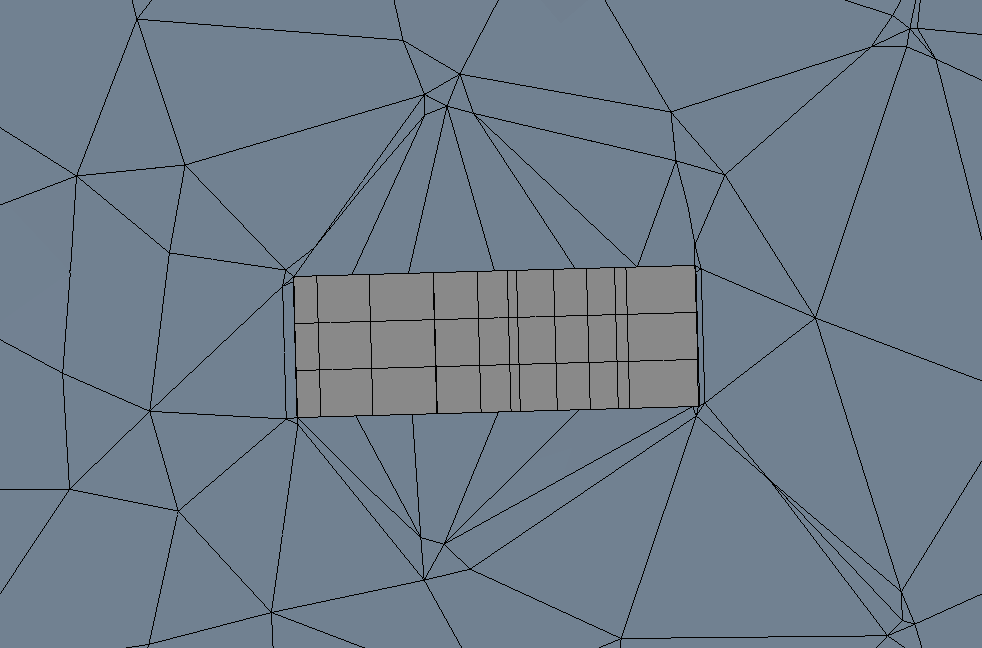
I'm working on a simulation of a polymer disc in a water enclosure, where a pressure source is applied to the top and side surfaces of the polymer disc, and its top surface is set to be fixed. I wonder if the default mesh created by harmonic acoustics would be accurate enough. I'm specifically concerned about the meshing around the interface between polymer and water. What the default mesh shows (the cross section of the mesh is shown in the screenshot below), includes a significant mismatch between the mesh cells in the polymer and the ones in water. I wonder if this can lead to inaccurate results, or the FSI boundary defined between the polymer top and side surfaces and the water enclosure would somehow insure the accuracy. If necessary, how can I avoid such mismatch between the mesh cells?
Also, I am trying to plot the deformation of the center point on the top surface of the polymer disc versus frequency as the simulation result. For this purpose, I have only been able to define a named selection by selecting a mesh node and then define the deformation plot to be evaluated on this mesh node point. However, this does not guarantee that the mesh node is in the center of the disc. Is there any way to do selection of a point other that mesh nodes, using its coordinates?
July 20, 2021 at 4:12 ampeteroznewman
SubscriberOpen the geometry in SpaceClaim. Start a sketch on the top of the disc. Draw two orthogonal lines across the diameter. A vertex will be created at the center of the face.
Use the Workbench tab and click on the Share button. The fluid and solid domain will have a matching mesh at the shared surfaces.
July 20, 2021 at 7:39 pmsadrip
SubscriberDear Thank you for commenting on this. I tried and did what you suggested, but I am having trouble making it work.
First, I draw the two orthogonal lines on top of the polymer disc (I'm using Design Modeler, since that is what I'm used to), but they don't show up in the geometry when I open the Model (please see the screenshots below). Therefore, I'm still unable to enforce the mesh to include the center point on the disc in the mesh nodes.
Also, I added the shared topology (third screenshot below), but it does not make the mesh matched between the polymer disc and the water region, so I'm still getting much coarser mesh in the water region, at the boundary between the disc and water. I'm not sure if there is any specific settings I should make for the shared topology though. It does not seem to have any options to choose the bodies, but it says 2 bodies in its properties (which is the total number of the bodies in my structure, so I'm thinking it might be okay.) I also noticed that there is a warning about the shared topology in Design Modeler, based on which the shared topology is not taken into account it seems like, and I don't know how to fix it (the last two screenshots below).
Is there anything I'm missing and I have to change in the settings?
Edit:
It just came to my mind that it might be necessary that I define a contact region under connection in Model. Is it? Previously, I had it generated automatically, but every time I ran the simulation, a warning showed up that one of the materials involved in that contact is acoustic region, and that it may be overwritten during the simulation.
(I have read some about defining contacts in the help documentation, but I am not able to find the situation where it is defined between acoustic and structural regions. )

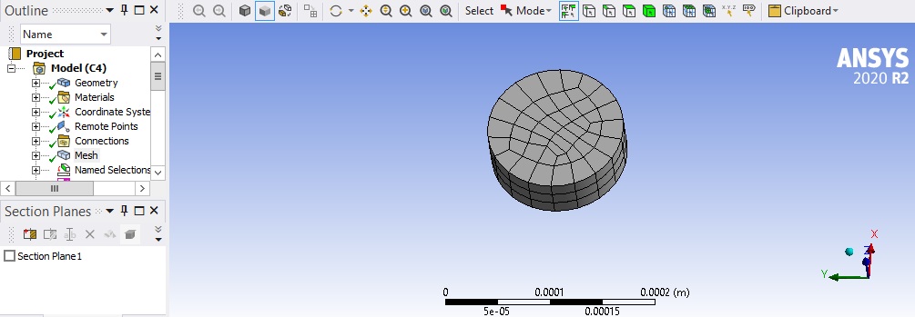
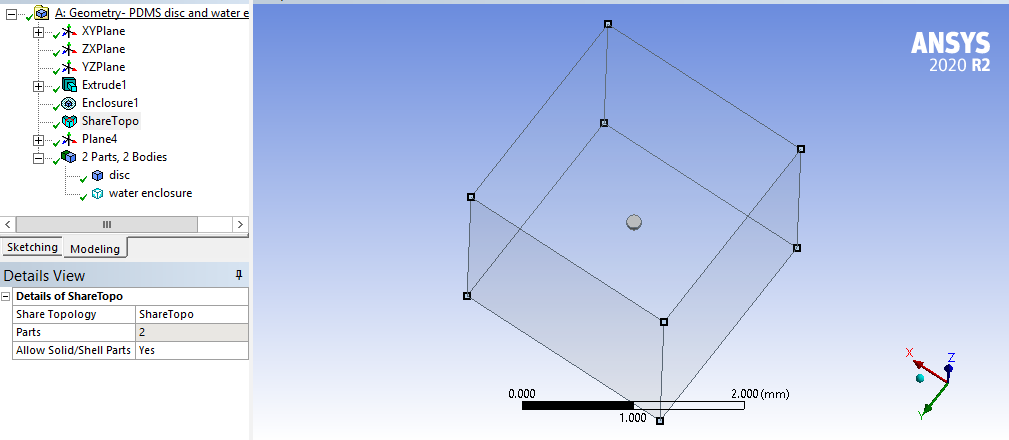
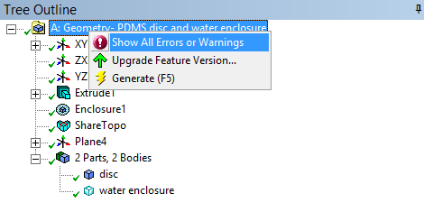

I appreciate it if you could share your opinion about these issues.
Thank you Parinaz
July 20, 2021 at 10:58 pmpeteroznewman
SubscriberDear Parinaz Design Modeler has more steps to accomplish the same effect that you can do with very few clicks in SpaceClaim.
Use Face Split and a Plane twice.
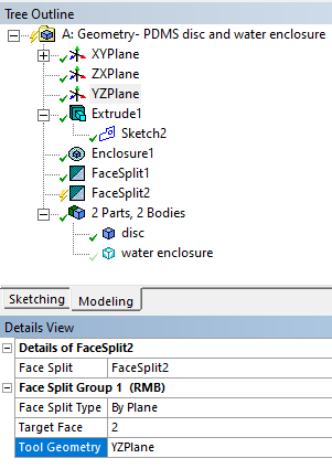
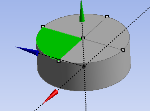 To Share Topology, you must select both bodies in the Outline then right click and select Form New Part.
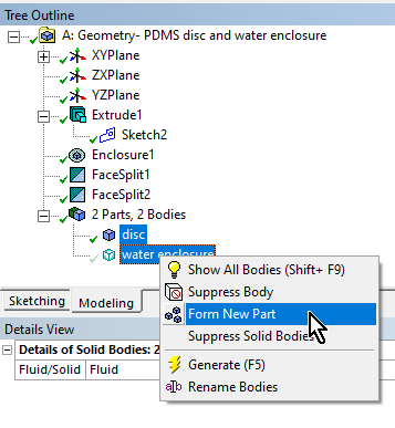
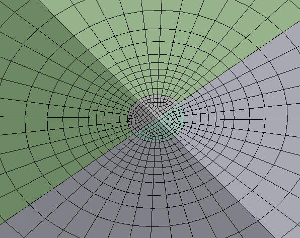
 Now the Shared Topology should work to make a congruent mesh. However, when I tried to mesh, it did not go well. I went back to DM and instead of split face, I used Concept Slice and sliced up the disk and the liquid body with 4 slices to make 12 pieces of liquid and 4 pieces of disc. Also, the enclosure will mesh more easily if it is also a cylinder not a box.
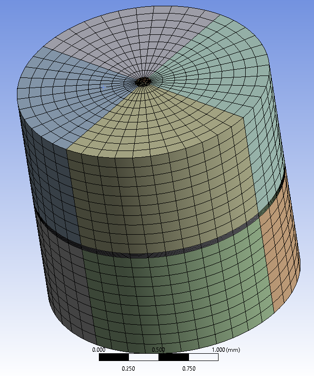
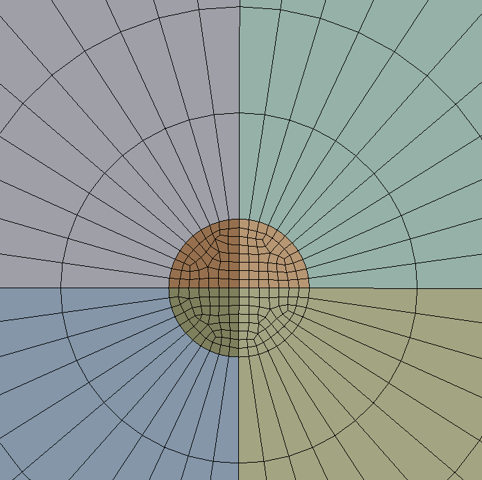 One improvement is to add a radial bias.
 July 21, 2021 at 12:26 am
peteroznewman
SubscriberP.S. When I tried to do the radial bias, I found the Shared Topology was not working. I took the geometry into SpaceClaim and did the Share and it worked properly.
July 21, 2021 at 5:46 amsadrip
SubscriberDear Thank you so much for your quick and extensive response.
I am still having some trouble fixing the meshing, and I really appreciate if you could comment on these issues:
1- When I Form New Part and use set the shared topology, I'm still not getting any matched mesh (1st screenshot below).I followed the exact steps based on your explanation, wondering what I might be missing.
2- Also, when I Form New Part, in the Model, the pressure source I have set to be on the top and side walls of the polymer disc starts to show a question mark on the left of its icon, seeming not to allow such surfaces to be set for the pressure source (2nd screenshot below).
Also, a couple questions regarding your explanation above:
3- Can you please explain the Concept Slice a little more? I'm not able to find it in Design Modeler. Do you mean the "Create -> Slice" option in the tool bar?
4- Also, I'm not understanding what radial bias means. Do you mean the mesh cells growing in size as it gets farther from the structure/acoustic boundary? Can you please explain where/how I should be setting it to happen?
Do you mind sharing the modified simulation file you generated where you have fixed the meshing issue? That'd be more helpful if you could.

 And here is the modified simulation file, for further reference:
Thank you so much Parinaz
July 21, 2021 at 5:47 amsadrip
Subscriber
July 21, 2021 at 11:56 ampeteroznewman
SubscriberDear Parinaz DM shared topology was unreliable for me also, use SpaceClaim. The Share button on the Workbench tab is very reliable.
The solids are renumbered in DM when you Form New Part or do a Slice, so Mechanical entities scoped to them will have to be repaired. The same thing happens when you use SpaceClaim.
Yes, in DM, it is Concept, Slice. In SpaceClaim it is Split Body, but you have to make a Plane first.
After configuring the slices to use a Sweep Mesh Method and putting Face Meshing to force hex elements, the Edge Sizing has a Bias parameter in the Details window.
Regards Peter
July 25, 2021 at 4:06 pmsadrip
SubscriberDear Peter Thank you so much for explaining. I'm going to try it in space claim. One more thing, I noticed that if I change the vibration source in this simulation, from pressure source on the polymer surface, to incident wave source, I get absolutely 0 deformation on the polymer disc surface. I have already defined the FSI boundary condition on the polymer/water boundaries, so I wonder why this happens. Could you please comment on this, too?
Please let me know if I should create a new post, since this is on a different aspect of the simulation.
Thanks Parinaz
July 25, 2021 at 6:20 pmpeteroznewman
SubscriberDear Parinaz Please create a new post to ask about acoustic loads. I am not an expert in that so I can't comment further.
Good luck Peter
July 27, 2021 at 8:51 pmsadrip
SubscriberThank you so much. I will ask that in a separate post then.
Viewing 10 reply threads- The topic ‘What is the accurate way to create mesh around FSI boundary in Harmonic Acoustics?’ is closed to new replies.
Innovation SpaceTrending discussionsTop Contributors-
4673
-
1565
-
1386
-
1231
-
1021
Top Rated Tags© 2025 Copyright ANSYS, Inc. All rights reserved.
Ansys does not support the usage of unauthorized Ansys software. Please visit www.ansys.com to obtain an official distribution.
-

