TAGGED: -Photonic-crystal, bandstructure
-
-
October 11, 2024 at 3:02 pm
Thanh.Nguyen
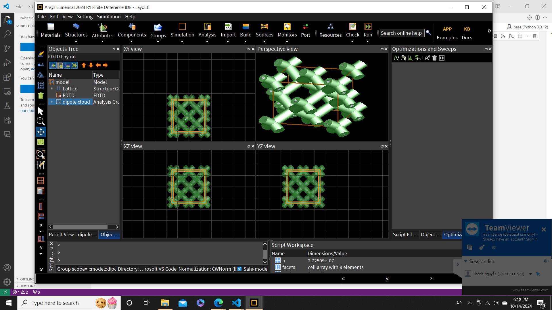
SubscriberI am running a simulation on a self-defined diamond structure. However, after running the FDTD, I received the band diagram that is different from theory as well as previous works. There is some weird band appeared as well as the position of the gap. I attached the simulation below.
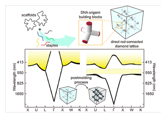
 -> This is my set-up, and I expect to see something similar to:
But I received
I am playing around with simulation area, k-vector but not really finding out what is the hinder reason
-
October 14, 2024 at 4:14 pm
Guilin Sun
Ansys EmployeeWe are not allowed to download customer files in the forum.
Please check the boundary conditions, and make sure the boundary is located exactly on the periodic location, and they should be Bloch. In addition, please check the polarization of the publication. Sometimes publication may only refer to one polarization but yours have all the dipole directions. But y-direction seems less efficient.
-
October 14, 2024 at 4:22 pm
-
October 14, 2024 at 6:16 pm
Guilin Sun
Ansys EmployeePolarization matters very much, except that a structure is rotationally symmetry along all directions.
When there are states inside the bandgap, it means the perfect structure is broken, either by the structure or polarization. Once you are sure there is no any issue for the structure (please use integer number of meshes along periodic axes with override mesh), you may need to modify simulation time/autoshutoff min to only pick the band signals. If the simulation time is too short, it may pick up non-band information; if it is too long, it may lose some low-Q resonance causing missing points on the bands. This needs trial and error to find a better simulation time.
I read the caption from the published figure: it says they use spheres in a high dielectric material. However your structure is not the same.
-
October 14, 2024 at 6:34 pm
Thanh.Nguyen
SubscriberThank you for your response! I tried with simulation time. I increased from 5000fs to even larger, but the band structure kept the strange states. I checked the structure multiple times and made sure it was correct. In the result, you may see that the weird band is not appeared at the band gap, but appears near to. As you read in the image, there are different structures, but I expect to have a similar form, which is in agreement with the other publications like in the bellowed works:
Design of DNA Origami Diamond Photonic Crystals | ACS Applied Bio Materials
https://www.researchgate.net/publication/325699065_Optimization_of_anisotropic_photonic_density_of_states_for_Raman_cooling_of_solids?_tp=eyJjb250ZXh0Ijp7ImZpcnN0UGFnZSI6Il9kaXJlY3QiLCJwYWdlIjoiX2RpcmVjdCJ9fQ
-
October 15, 2024 at 7:53 pm
Guilin Sun
Ansys Employeeit seems it has end caps (in red), and their angles is not 90 deg. Make sure the structure AND the materials are exactly the same as the paper. Any difference can lead to different result.
For band structure simulations, as long as the structure, periodicity and boundary conditions are correct, and the mesh size is period/N where N is an integer, usually you will get very close result to publications. SImulation time is just to refine the result. too short or too long are not good.
Other than those points, I could not see any other causes of the large difference, in particular inside the bandgap. When there are photon states inside the bandgap, it means the periodicity is broken.
I summarized general causes here
Ansys Insight: Why my simulation result is different from published paper or experiment?
-
October 15, 2024 at 8:17 pm
Thanh.Nguyen
SubscriberThe angles between hands in tetrapod are ~105.9 degree, which is similar to my structure. The current mesh is uniform with 20 mesh cells in each dimension. I also tested with 50, but nothing changed. In the image of a first reply, you can see the simulation area where I applied Bloch boundary condition, it should preserve the periodicity. I think the problem is not from broken periodicity because the weird band is not within the band gap. P/S: I tested with different polarizations, as my first guess, it returned the same result
-
October 16, 2024 at 5:39 am
Thanh.Nguyen
SubscriberNever mind! Problems solved! Thank you a lot for your help! :)
-
- You must be logged in to reply to this topic.


-
4803
-
1576
-
1386
-
1242
-
1021

© 2026 Copyright ANSYS, Inc. All rights reserved.


