TAGGED: -waveguide
-
-
September 3, 2024 at 3:13 pm
amoghbs
SubscriberHi,
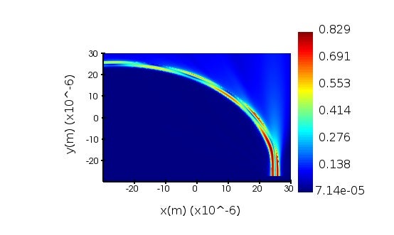
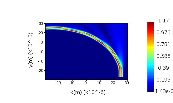
I am trying to understand scattering loss for a 2nd TE mode in a bend when transitioning from a straight waveguide mode to a bent one with specific waveguide dimensions, 2.4um in width and 80nm in depth and bend radius of 50um. I did the simulations in both FDFD (mesh accuracy 4) and varFDTD (mesh accuracy 5) but I am getting different transmission even though I think both are identical otherwise. I expected both the results to be different but the difference in T is too big (29% - FDTD vs 85% - varFDTD) . The susbtrate in my sims in 7um silicon, with a 2um SiO2 layer on top, and a dielectric with refractive index of 2.27 with thickness of 220nm and finally the waveguidees on top made of the same dielectric. I have attached the image of the sim setup and cross sectional E field plots. Could you please help me with this? -
September 9, 2024 at 3:31 pm
Ethan Keeler
Ansys EmployeeHi Amogh,
It's a bit difficult to diagnose the issue without being able to directly consider your simulations files; however, here are a few topics to consider:
- The MODE Source span should be large enough such that the fields have decayed to ~1E-05 of the peak value at the edges. This will avoid significant clipping of the mode energy.
- We also recommend that there is a lambda / 2 distance from the source to the PML boundaries.
- The mesh accuracy of 4 seems pretty reasonable already, but you could try increasing it to 5 to see if there is a significant change in the result. This will allow you to do a bit of convergence testing on the result to find the best choice for the mesh. You could also add index monitors in your two simulations to see how resolved the bend is.
Hopefully some of these pointers can help in reconciling the two simulations.
Ethan
- The MODE Source span should be large enough such that the fields have decayed to ~1E-05 of the peak value at the edges. This will avoid significant clipping of the mode energy.
-
September 10, 2024 at 4:26 pm
amoghbs
SubscriberThanks for the reply. Is there a way I could share the files with you?
-
September 11, 2024 at 7:00 pm
Guilin Sun
Ansys EmployeeEthan is in conference so I take over.This post is the same as this FDTD vs varFDTD (ansys.com).
While ideally varFDTD can be the same as 3DFDTD, in some cases, or in most cases they may not give the same result. This is because, varFDTD decomposes the original 2D mode into two 1D modes, eg, E(y,z)=E(y)*E(z), so only when it can be exactly decomposed in this way througout the whole device can the results be identical.
That said, usually varFDTD is used to get a quick result. 3D FDTD should be more accurate, and we strongly recommend users to have 3D FDTD for final verification.
As you can see from the two screenshots, the scattering is different: varFDTD has only 1D scattering whereas 3D FDTD has 2D scattering, eg, along the waveguide wall.
To improve accuracy, you may increase the mode-source/monitor size and make sure no mode field is clipped.
-
- You must be logged in to reply to this topic.


-
4683
-
1565
-
1386
-
1242
-
1021

© 2025 Copyright ANSYS, Inc. All rights reserved.


