-
-
August 29, 2023 at 11:49 am
ghislain_madiot
SubscriberHi everyone,
I am currently engaged in a university project where my focus has been on developing a wave rotor model within ANSYS Fluent. This model encompasses a rotor made up of an array of channels, flanked by static ports on both sides. To optimize computational efficiency, I opted to model just one radial cell, ensuring symmetry at the top and bottom through boundary conditions. This choice was motivated by the time-intensive nature of running numerous cases, and I am actively seeking ways to streamline this process.
In the described model, the radial dimension remains constant, resulting in a 2D scenario in cylindrical coordinates. Consequently, I projected the geometry onto a 2D Cartesian plane for use in Fluent. I then endeavored to configure a purely 2D planar model within Fluent.
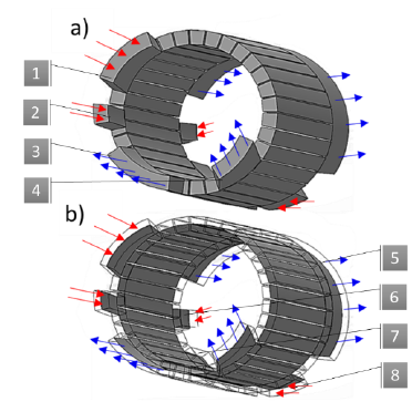
The figure attached represents the domain I am trying to model.
the computational domain is divided into three fluid segments: two stators on the left and right-hand sides, and the rotor composed of channels. Each domain exhibits a periodicity of 1, reflecting their projection across a complete revolution. To establish connectivity between the rotor and stator domains, interfaces with periodic repetition are defined. Furthermore, periodic matching is applied at the top and bottom boundaries to connect the channels on both ends and to link the ports.
For the rotating channel domain, a moving mesh approach is employed to replicate tangential velocity rotation (in Y direction). The inlet and outlet boundaries are designated as pressure inlet and outlet, maintaining a constant pressure.
However, I'm currently facing an issue where the rotor domain no longer seems to be connected to the ports. This prompts my questions: Is this approach feasible within Fluent? How should I properly set up the boundary conditions?
I'd also like to mention that I came across a paper ( https://www.sciencedirect.com/science/article/pii/S0196890422013565), which presents a concept closely aligned with my objectives. However, the paper employs ANSYS CFX for CFD simulations. Based on my understanding, CFX lacks a dedicated 2D solver, which seems to result in an element being generated in the direction of the normal vector, akin to my initial model (though I acknowledge I might be mistaken in this comparison).
Thanks in advance for your help and your advice,
Regards,
Ghislain
-
August 29, 2023 at 1:07 pm
Rob
Forum ModeratorCFX doesn’t have a 2d solver so assumes the domain is one cell thick. Fluent does have a 2d solver so then works on faces rather than volumes.
Flattening to true 2d in Fluent may break the rotational periodic option that you’re trying to mimic. You may need to create a curved 3d model but set inner & outer annular faces as symmetry and have only one cell in the radial coordinate. You can then follow the turbo examples for the rotor-stator configuration. Note, check the interface settings to ensure you’re retaining the data on both sides of the interface: you don’t want any averaging!
-
August 29, 2023 at 3:56 pm
ghislain_madiot
Subscriber-
August 30, 2023 at 8:34 am
ghislain_madiot
SubscriberHi Rob,
Thanks for your response. If I have understood your response correctly, I have previously developed a similar model. I’ve created a “Q2D model” (as shown in the figure) in comparison to the traditional 3D approach.
This model contains a singular cell in the radial direction, with symmetry boundary conditions at the upper and lower faces, as well as a sliding mesh at the rotor/stator interface. If this aligns with your scenario you advised, I might encounter similar computational time challenges, which is why I’m considering transitioning to a 2D approach.
I came up with two two potential ideas, though I’m uncertain about their feasibility.
Firstly, based on my research, prior studies have employed multiple replications of the stator ports, wherein the cycle occurs as the rotor domain moves upward. However, the drawback of this method is the necessity to replicate as many ports as cycles required to achieve a steady-state pattern in the rotor.
Could it be possible to establish a repeated symmetry for the stator domain in order to have a correct flow distribution when channels pass?
Another concept involves translating the mesh upon crossing the “periodic line.” If each channel possesses its own domain, could it be feasible to reposition each mesh block to its initial location when they surpass a specified value in the Y-axis? This approach would mimic the moving channel mechanism while preserving fluid characteristics.
Nevertheless, if CFX offers the potential for a significant breakthrough, I’m open to transitioning to it and mimic the process outlined in the paper referenced above.
-
-
August 30, 2023 at 8:45 am
Rob
Forum ModeratorAssuming something happens in the flow cells on the rotor when they're not connected to the flow ports I'd probably go with the 1 cell thick annular pseudo 2d option, second image above. Not least as I can't see any symmetry or repeated section in the stator. With 2023R2 I think Student is good for 1M cells, and I'd expect most laptops to have 4-8GB RAM and 4 useable cores so all good. Overall run duration then comes down to how big the time step is and how long a duration is required.
-
- The topic ‘Wave Rotor Modeling in ANSYS Fluent: BC definition and 2D Feasibility’ is closed to new replies.


-
4718
-
1565
-
1386
-
1242
-
1021

© 2026 Copyright ANSYS, Inc. All rights reserved.


