TAGGED: 2D, ansys-fluent, boundary-conditions, convergence, fluid-dynamics
-
-
July 14, 2021 at 6:06 am
surajgarad
SubscriberI need to do wave generation for deep water condition in 2d or 3d. I think 2D is sufficient.
I have tried with fines mesh like 100 cells per wavelength and 20 cells per waveheight.
The basic requirements are, deep water conditions, wave shouldn’t get damped, first order airy theory and K-w SST model for turbulence.
For wave generation I have used open channel wave BC, Implicit body force and Sharp from interface modelling. Interfacial Anti-diffusion is also ticked.
In order to avoid reflection from opposite wall, numerical beach is provided over two wavelengths from opposite wall.
For Pressure- Velocity coupling SIMPLE scheme is used, Pressure – PRESTO, momentum - second order upwind, Volume fraction – Modified HRIC, Turbulent K.E- second order upwind, Sp. Dissipation rate – second order upwind, transient formulation – second order implicit.
For very low values of k and w (1e-06), the wave is not getting damped and I am getting expected results but when I am initializing simulation with calculated values of k and w, it gets damped.
For reference, I have followed
1) Numerical simulation of an oscillating water column device using a code based on Navier - Stokes equations.
2) CFD modelling of a small–scale fixed multi–chamber OWC device
3) Fluent user manual
4) Fluent user guide
5) Scaling and air compressibility effects on a three-dimensional offshore stationary OWC wave energy converter
6) Tutorial: Heave and Pitch Simulation of Ship hull moving through head sea waves.
July 14, 2021 at 1:00 pmRob
Forum ModeratorWhen you say initialised with values for k & w how long are you running the model to determine if the waves are being dissipated?
July 14, 2021 at 1:09 pmsurajgarad
SubscriberThanks for the reply I am running simulations for nearly 20 wave cycles or crests. From the first wavelength itself, it starts damping.
July 14, 2021 at 1:22 pmRob
Forum ModeratorHow deep is the domain, and how much space is there above the water level? Is the model converging, and how are you defining k & w on the boundaries?
July 14, 2021 at 1:30 pmsurajgarad
SubscriberI have taken a domain length of 20 m ( to have a sufficient number of peaks in a domain )and a water depth of 2 m considering deep water conditions. I have given waveheight of 0.15 m with the time period of 1.0769 sec, the mean level is at zero. First I have defined very less values (1e-06) for k and w, in that case, I got an undamped wave with a converged solution but when I am using calculated values (used an online calculator) for k and w values, the solution is getting converged but wave got damped.
July 14, 2021 at 2:07 pmRob
Forum ModeratorWhere are you using the calculated values of k & w?
July 14, 2021 at 3:37 pmsurajgarad
SubscriberAt the inlet (left side) where I am using open channel BC for generating a wave
for the right side where pressure outlet is defined and top side with pressure outlet boundary condition.
July 15, 2021 at 4:59 amsurajgarad
SubscriberI am using calculated k and w values at inlet, top and outlet.
July 15, 2021 at 11:11 amRob
Forum ModeratorWhat values are you using? If you plot the k & w values in the earlier model and compare with this case how does it look?
July 15, 2021 at 11:58 amsurajgarad
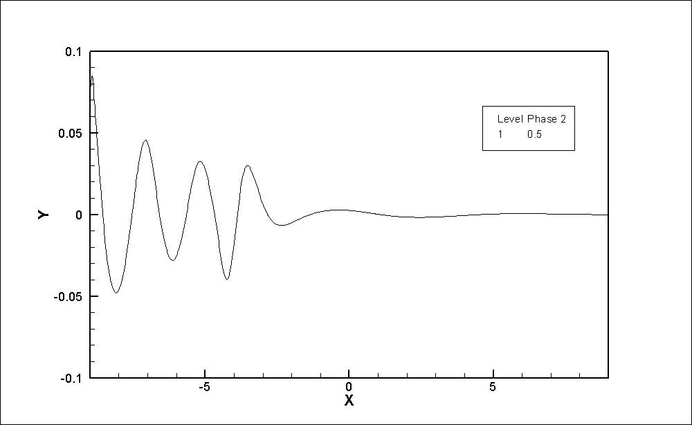
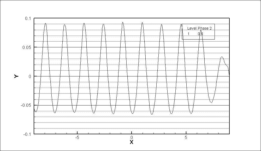
SubscriberFor undamped wave case, the values of k and w were very less i.e. 1e-06
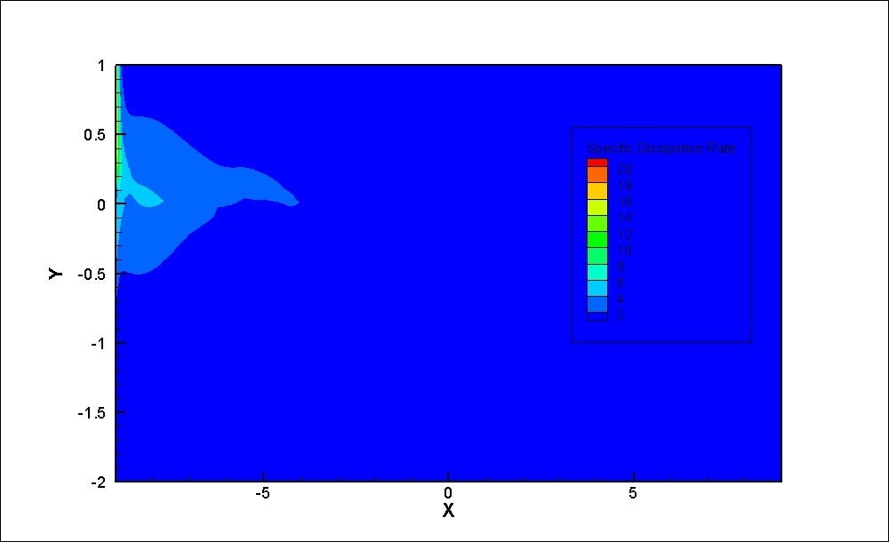
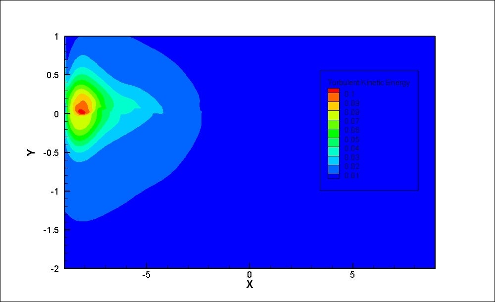
For damped case, k = 0.0106 and w = 0.05 (it is calculated from cfd online calculator https://www.cfd-online.com/Tools/turbulence.php )
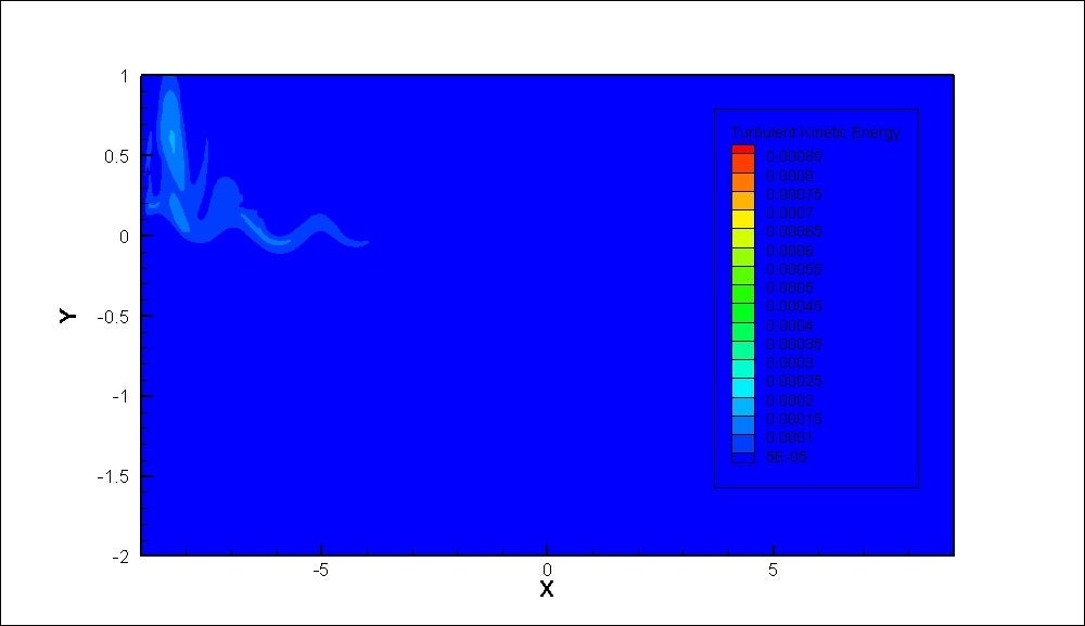
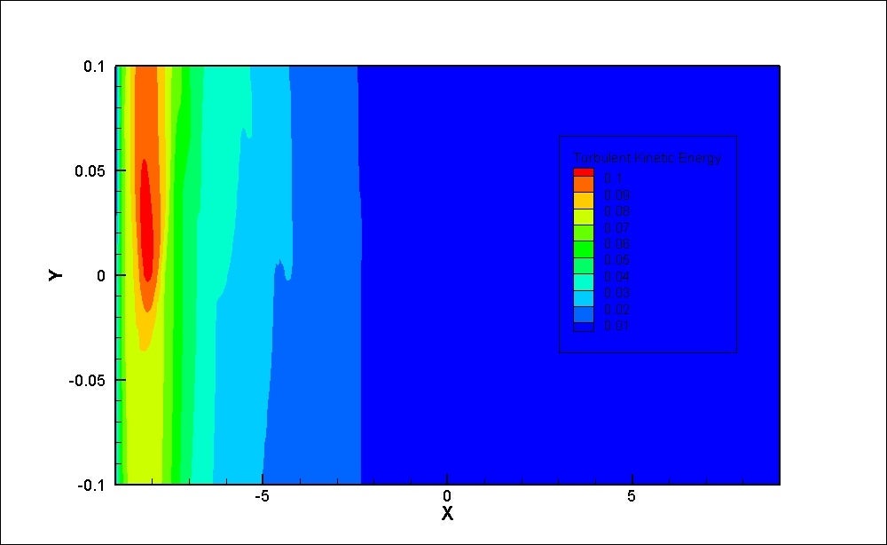
I have attached plots of k for reference.
July 15, 2021 at 12:44 pmRob
Forum ModeratorStaff are not permitted to open or download attachments, please add in line with the text.
July 15, 2021 at 12:59 pmsurajgarad
SubscriberFor undamped wave case, the values of k and w were very less i.e. 1e-06
For damped case, k = 0.0106 and w = 0.05 (it is calculated from cfd online calculatorhttps://www.cfd-online.com/Tools/turbulence.php)
I have attached plots of k for reference.

July 15, 2021 at 12:59 pmsurajgarad
Subscriber
July 15, 2021 at 1:09 pmRob
Forum ModeratorWhere's the free surface?
July 15, 2021 at 1:12 pmsurajgarad
SubscriberAt 0 in y direction
July 15, 2021 at 1:16 pmRob
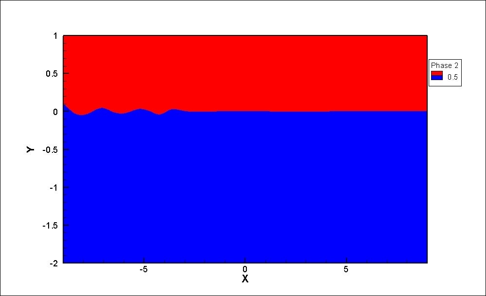
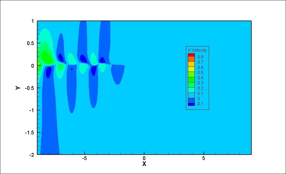
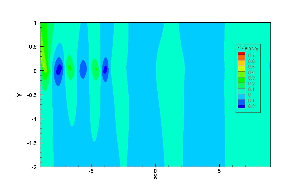
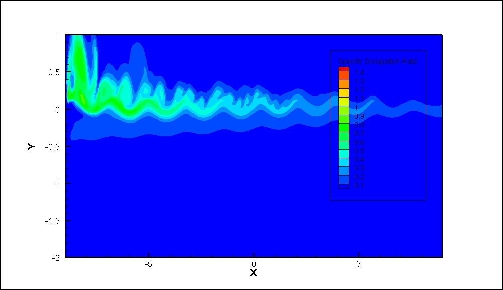
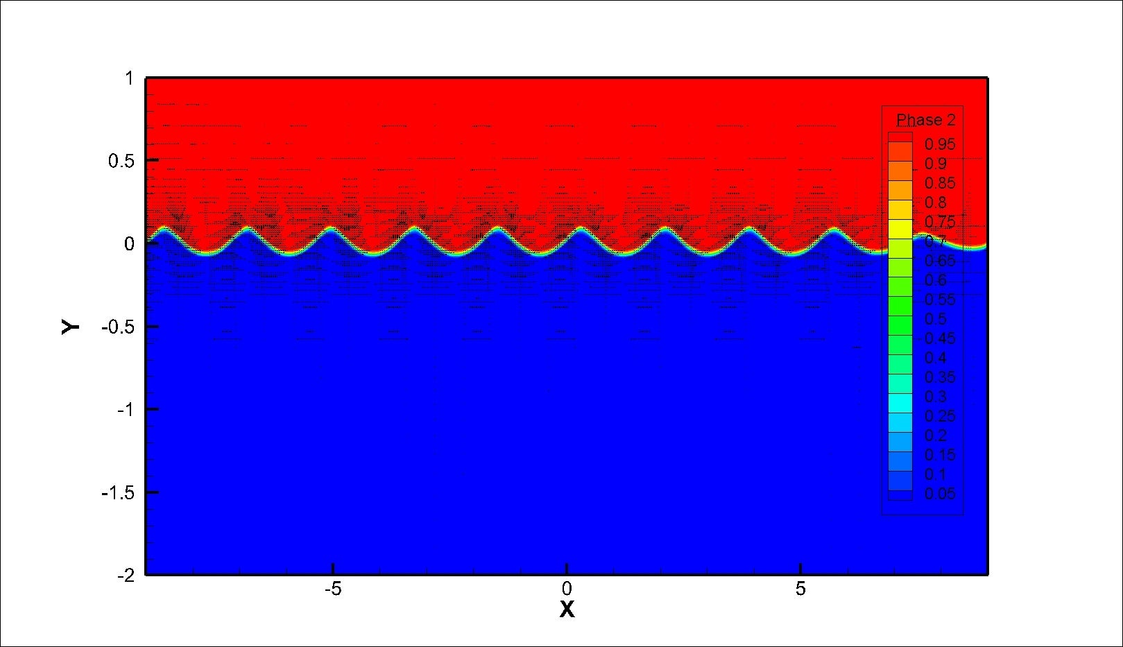
Forum ModeratorPictures? At the moment you have a domain that's 20cm high and 20m long with no waves and a turbulence field that's very quickly damped out. Please add enough data so we can actually see what's going on.
July 15, 2021 at 1:27 pmJuly 15, 2021 at 3:05 pmRob
Forum ModeratorYou may have over constrained the model, make the domain significantly higher in the y dimension so the boundary values don't unduly influence the flow and see what that does.
July 15, 2021 at 3:49 pmsurajgarad
SubscriberOk, I will try with a higher domain in the y-direction. But is I need to increase cell count or can I keep the same?
July 16, 2021 at 4:29 amJuly 16, 2021 at 11:12 amRob
Forum ModeratorCan you plot the phases so we can see the waves, the velocity field and also phases with node values off.
July 16, 2021 at 1:08 pmJuly 16, 2021 at 2:50 pmAmine Ben Hadj Ali
Ansys EmployeeDomain extents epscially above the free surface is very important: Please use there at least 1.5 or two wave length to put the top boundary.
July 16, 2021 at 2:52 pmAmine Ben Hadj Ali
Ansys EmployeeAlso use good initial values based on the Phase: this is possible with 21R1 and later.
July 16, 2021 at 2:54 pmAmine Ben Hadj Ali
Ansys EmployeeProbably turbulence damping is required at the interface too.
July 17, 2021 at 5:53 amsurajgarad
SubscriberHere we have license for Ansys 20, can you explain how to provide turbulence damping at interface. I will check with 1.5 m distance between top and free surface.
July 19, 2021 at 11:13 amRob
Forum ModeratorI assume you mean 2020Rx? It's an option in the Turbulence (Viscous) panel.
July 19, 2021 at 11:48 amsurajgarad
SubscriberOhh. Is it fine to go with default value for turbulence damping, under relaxation factor and k w values?
July 19, 2021 at 12:40 pmAmine Ben Hadj Ali
Ansys EmployeeYes: that is fine. If you do not measurements or power to do a sensitivity analysis stick to defaults.
However as mentioned I recommend that you test with phase sensible turbulence field initialization first + extending the top boundary away from free-surface
July 21, 2021 at 10:06 amsurajgarad
SubscriberI have checked simulation with extended top boundary and with default values of turbulence damping, URF and k -w values. Still wave get damped.
July 21, 2021 at 12:16 pmAmine Ben Hadj Ali
Ansys EmployeeTurbulence Field initialization used?
July 21, 2021 at 12:27 pmsurajgarad
SubscriberYeah, I have one small doubt, normally I am giving k-w values at the inlet boundary, pressure outlet, and at the top side. Is it ok to define k w values at three boundaries or have to provide only at the inlet boundary conditions?
July 21, 2021 at 12:31 pmRob
Forum ModeratorYou define k & w for any and all flow boundaries.
July 23, 2021 at 5:06 amsurajgarad
SubscriberI have defined k and w at all boundary conditions. Distance between top boundary and free surface is also increased. Still wave get damped. From the console the recommended theories are nonlinear or stokes theories but I need to use linear/airy theory. Is that arising issue? or is there any problem with solution methods?
July 23, 2021 at 6:31 amAmine Ben Hadj Ali
Ansys EmployeeAt wall boundaries? How have you done that?
I recommend using Stokes Theory and check the results you are obtained.
July 26, 2021 at 1:37 pmsurajgarad
SubscriberI have checked with both linear and stokes theories, the wave height got damped. How the values of k and w affect the simulations, means to what level? I think k and w values only making trouble.
July 31, 2021 at 9:09 amsurajgarad
SubscriberHi I am still struggling to get results. Can you confirm is I am using correct boundary conditions and methods?
August 2, 2021 at 9:51 amAmine Ben Hadj Ali
Ansys EmployeeYou wrote you are assigning values for k and omega at walls? How did you do that ( I am asking as this will require rewriting the wall functions).
Again: Are you using localized turbulence initialization? Are you tracking the max velocity in the domain? Which are now the domain extents? Which is now your time resolution? Are you using numerical beach: if yes disable it if no is there a difference if you enable it
Which version are you using?
Which are the scenarios where the waves are not dampened?
Goal is that you summarize the issue in single post.
August 2, 2021 at 10:59 amsurajgarad
Subscriber1) Yeah, I have tried with default value and with calculated values at velocity inlet and pressure outlet, not at a wall boundary.
2) Localized turbulence initialization means I am defining only on surfaces (as now performing 2D simulations so line) Domain extents are taken to have atleast 7-8 peaks (-10 to 10m). Here I have considered adaptive time stepping 1e-05 to 1e-03. Yes I have tried both with numerical beach and without beach also. In both cases it gets damped. From starting itself, means at a distance of one wavelength, wave starts getting damped so couldn't say much about effect of numerical beach.
3) Fluent 18.1 and Fluent 2020
4) K- w values of 0.02 and 2, Stoke 5 theory,
I have tried with fines mesh like 100 cells per wavelength and 20 cells per waveheight.
For wave generation I have used open channel wave BC, Implicit body force and Sharp from interface modelling. Interfacial Anti-diffusion is also ticked.
In order to avoid reflection from opposite wall, numerical beach is provided over two wavelengths from opposite side.
For Pressure- Velocity coupling SIMPLE scheme is used, Pressure ÔÇô PRESTO, momentum - second order upwind, Volume fraction ÔÇô Modified HRIC, Turbulent K.E- second order upwind, Sp. Dissipation rate ÔÇô second order upwind, transient formulation ÔÇô second order implicit.
5) Basic requirements are: deep water conditions, first order airy theory, k w sst model
August 2, 2021 at 12:33 pmAmine Ben Hadj Ali
Ansys EmployeeCan you use Compressive Scheme instead of HRIC.
Can you try with 21R1 or 21R2?
With localized Turbulence is something different I meant: To start with turbulence fields relative to phase volume fraction field. This is directly possible with 21R1
If you are still seeing damping issues without beaching with Compressive Scheme on your 2D runs: please report and provide an academic contact address.
August 2, 2021 at 12:37 pmsurajgarad
SubscriberOk, I will try with compressive scheme and let you know the results.
We have license for Ansys 2020 version.
March 19, 2022 at 12:16 amwangkai1
SubscriberHi´╝îHave you solved the problem? I also met the same problem. How did you solve it´╝îplease´╝ƒthank you´╝ü
October 26, 2022 at 3:23 pmNazmul Islam Nishat
SubscriberHow to generate wave properly for owc ....?i need full tutorials.if any one give me suggestion or give me video how to do it. thnx
Viewing 42 reply threads- The topic ‘Wave generation in deep water (wave is getting damped)’ is closed to new replies.
Innovation SpaceTrending discussionsTop Contributors-
5044
-
1749
-
1387
-
1248
-
1021
Top Rated Tags© 2026 Copyright ANSYS, Inc. All rights reserved.
Ansys does not support the usage of unauthorized Ansys software. Please visit www.ansys.com to obtain an official distribution.
-

