-
-
July 25, 2024 at 3:05 am
abdullahhassan
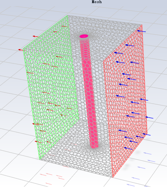
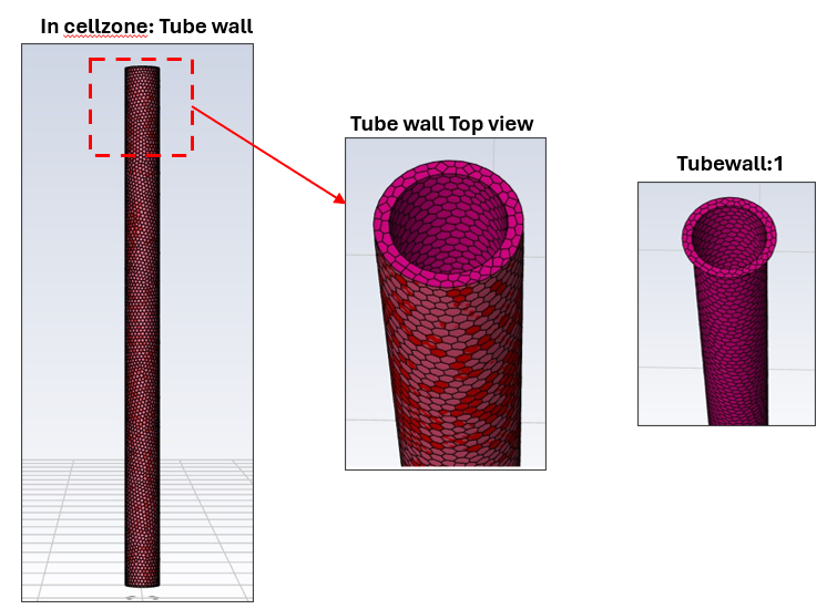
SubscriberHi, I am trying to simulate Multiphase condensation on a single tube. Below is my geometry image.
I use Multiphase > VOF > Implicit > Sharp > Evaporation—condensation at 300K with 500 condensation frequency as a condensation model with transient flow. The gravity is -9.81.
Tube wall temperature is 273.15K from Cell Zone > fixed values.
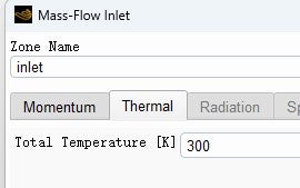
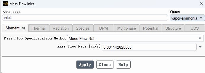
Inlet = mass flow rate of Vapor Ammonia is 0.00414282Kg/s with a temperature of 300K and a pressure of 1061700Pa.
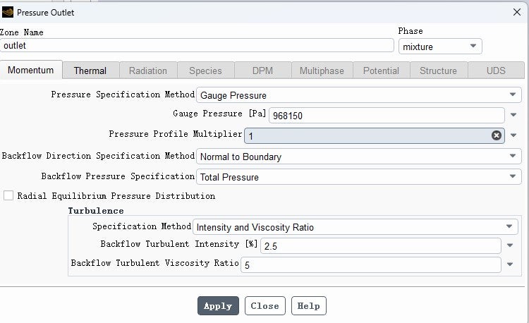
Outlet = backflow temp = 297K with Backflow VF = 1. Pressure = 968150Pa.
The pressure, thermal conductivity, etc., are taken from REFPROP at saturation temperature.
Hybrid initialization with an initial patch of vapor in the whole domain.
I have done many variations but the volume fraction I am getting is very very low . how can I improve the volume fraction?
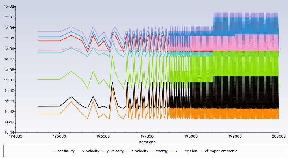
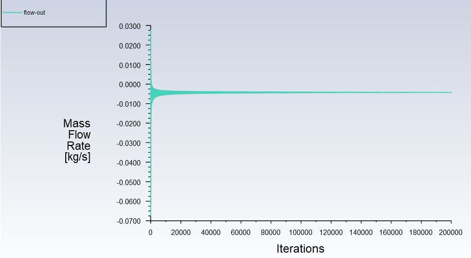
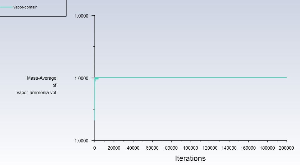
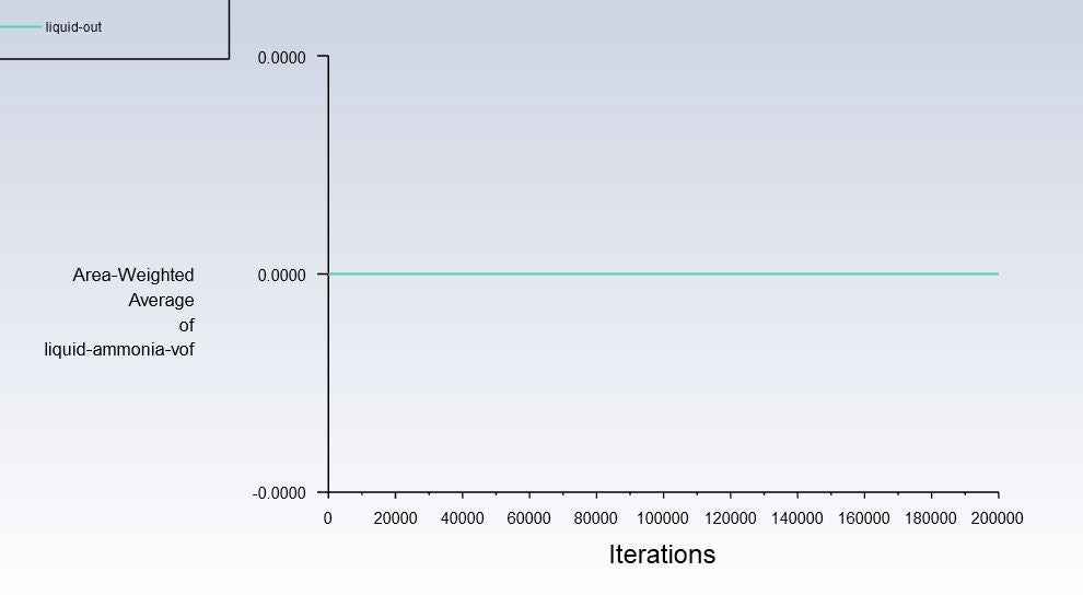
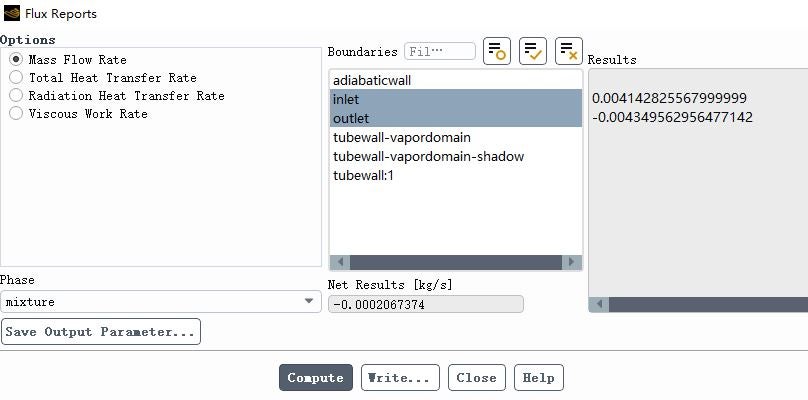
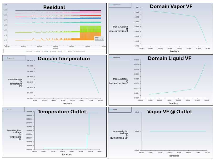
I have share residuals, mass flow rate (in/out), vapor in domain(100%), Liquid out (0%), heat fluxes. what do I need to share more?
-
July 25, 2024 at 9:22 am
Rob
Forum ModeratorI'd remove the solid and apply a thermal wall boundary condition, less mesh and possibly easier to control.
How much liquid are you expecting, and given VOF is a free surface model do you think it's the best choice?
-
July 26, 2024 at 1:50 am
abdullahhassan
SubscriberHi Rob,
I am expecting atleast 60% of liquid VF in simulation. it is a simple setup and next step is to simulate condensation over multiple tubes.
Regarding choice of VOF model, majority of papers have used VOF to simulate condensation that's the reason i am using.
By thermal wall boundary condition, did you mean coupled wall or using heat flux? this is the condition i have applied.
Also at cell zone>tubewall>fixed terms > 273.15K. just to make sure the tube pipe will remain subcooled for condensation.
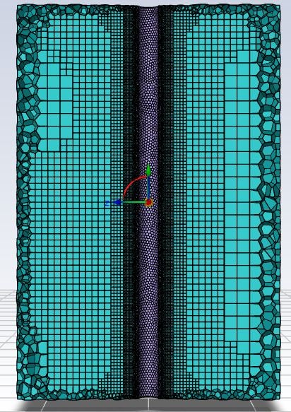
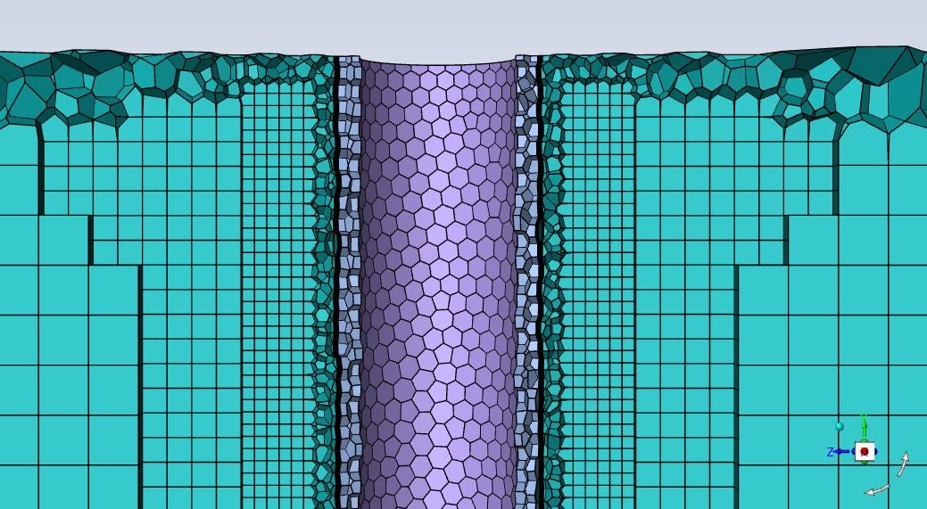
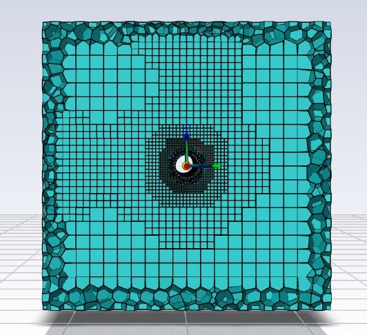
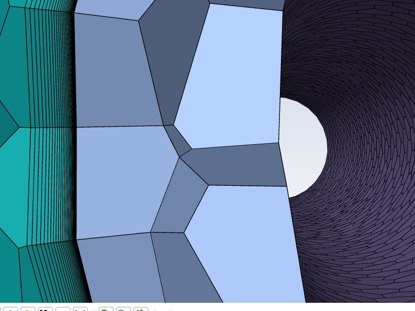
let me also share the mesh of this geometry, as i am also not confident on the mesh too.
for the volumetric mesh, min size = 0.3mm, max size is 9.6mm , inflation layers 25 with first layer at 0.005mm and growth of 1.1. orthognal quality of 0.2.
-
July 28, 2024 at 11:59 am
abdullahhassan
SubscriberIn addition to the above case, can you clarify me about latent heat? Supposing the value of latent heat at 300 K is 1.972e7, with LIQUID in the From phase and VAPOR in the To phase, the SSE should be positive to avoid "error: latent heat should not be negative". Do this thing have some link to condensation?
Am I doing an evaporation instead of condensation?
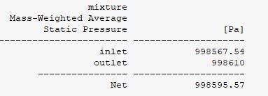
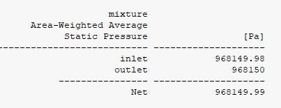
Secondly, I just observed that the pressure itself is nearly constant which means at the outlet, the pressure is not decreasing which I think maybe also a reason for condensation not happening or very slow condensation.
the inlet pressure was 1061700pa @ 300K and outlet pressure I put was 998150Pa @ 297K. after simulation. below is the pressure now
-
July 29, 2024 at 10:42 am
Rob
Forum ModeratorFluent doesn't know which material is liquid and which is vapour in the mass transfer field, so there is a convention regarding the from & to fields. It's in the User's Guide, and is something I always have to look up. If you click on Help in the Mass Transfer tab it'll take you to the panel help, and from there to the setup.
Fixing the solid region temperature may not be sensible. Check the wet side wall temperature and also near wall cell temperature to see what's going on.
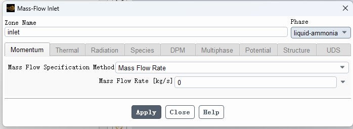
If you have near enough zero pressure loss check the mass flow: what are you setting on the inlet?
-
July 30, 2024 at 7:16 am
abdullahhassan
SubscriberHi,
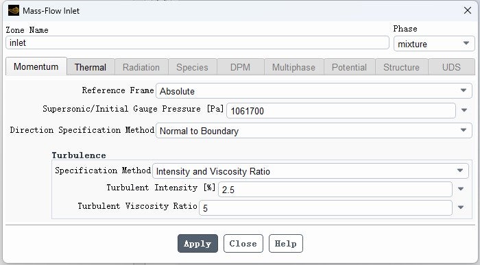
below is the inlet BC.
Below is the outlet BC.
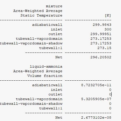
For side wall temperature: as temperature was fixed at 273.15K . you can see the volume fraction and temperature in below screenshot. even at tubewall_vapordomain, the volume fraction is too low but saturation temperature is 300K.
Point to note:
1- after some iterations, my pressure inlet outlet values become same which is 968150Pa. as per setting this is outlet pressure and inlet pressure is 1061700Pa. i don't understand why.
2—In multiple simulations, sometimes mass flow remains the same or shows a minor change at the outlet. Sometimes, mass flow at the outlet increases drastically, but in this case, mass flow is not changing.
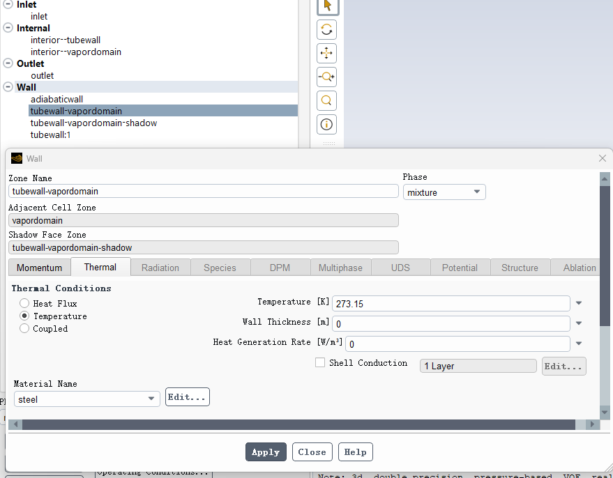
3—As you suggested, I have turned off the fixed temperature from the cell zone and want to apply convection at the near-wall BC. Are you suggesting that I put a temperature value at the Tubewall_vapordomain interface or at tubewall1, which is the innermost wall of the tube?
-
July 30, 2024 at 8:45 am
Rob
Forum ModeratorRe-read the inlet pressure option you've picked as it's not going to do anything in this scenario. The inlet pressure is whatever is required to push the vapour mass into the domain against the outlet pressure.
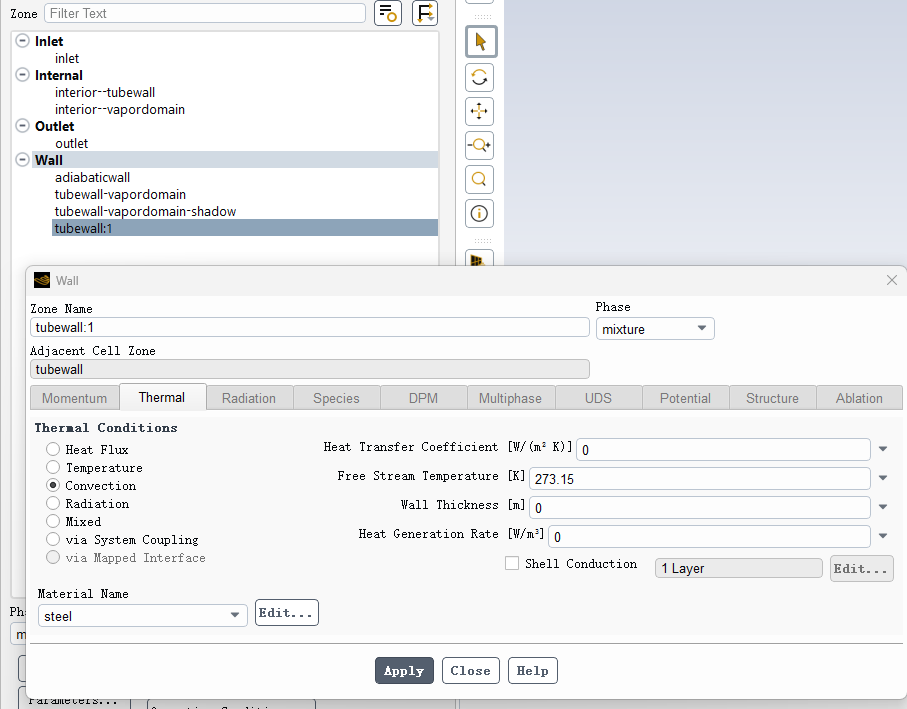
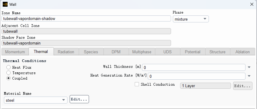
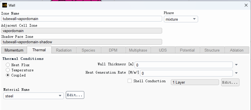
For this I'd tend to set the "outside" tube wall (wet tube side boundary) as you have above but with an HTC and temperature that's appropriate to the system - there are correlations for horizontal & vertical tubes in the literature. If you can't find a value go and ask a Chemical Engineer nicely as it's in most of the first year text books. Retain the "coupled" setting on the wall-wall:shadow pair otherwise there's no heat transfer.
-
July 30, 2024 at 9:28 am
abdullahhassan
SubscriberDo you think, is there any other model which is better then the VOF for condensation?
In the longer run, I need to perform the same simulation on a complex heat exchanger design. Should I use UDF?
-
July 30, 2024 at 9:51 am
abdullahhassan
SubscriberThank you Sir,
I understand your point for using HTC value. I will try this way and will let you know.
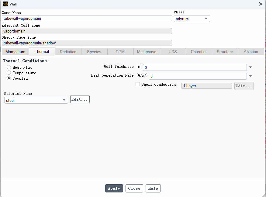
1- shadow wall will be set to coupled as shown below:
2- If I choose coupled at the "outside" tube wall (wet tube side boundary), how can I choose HTC ? below is the BC setup.
3- last thing, what is meant by re-read the inlet pressure?
-
July 30, 2024 at 10:17 am
Rob
Forum ModeratorYou have a solid tube in the model, so the wall & shadow pair are between the fluid & solid. There’s then an exterior wall which may be tubewall:1 that’s where you set the tubeside free stream temperature & wall HTC.
Read the mass flow inlet panel carefully: what is the pressure you’re setting?
For condensation Eulerian Multifluid is an option, for low levels of condensation Eulerian Wall Film can be used.
-
July 31, 2024 at 1:20 am
abdullahhassan
SubscriberThank you Sir,
Currently, i am setting pressure 1061700Pa as per P-T saturation curve for temperature 300K. Similarly the outlet pressure is 968150Pa for 295K.
In Eulerian Multifluid VOF model, Lee vs Thermal Phase change, which model is preferrable for mass transfer.
One more thing that comes into my mind right now, for how long, i need to keep the simulation running? the condensation is happening but at very slow rate and if i see the residuals, they are all flat or changing at very slow rate. should i give much more time to the simulation like weeks?
my current timestep size is 1e-5 with max iteration/timestep of 20. scheme is Implicit.
-
July 31, 2024 at 9:05 am
Rob
Forum ModeratorBoth schemes are good, but there are some constants that may need tuning. Bear in mind you need the domain to reach an equilibrium, given the flow speed and time step, how many steps do you need to get flow from the inlet to the outlet?
-
July 31, 2024 at 11:40 am
abdullahhassan
Subscriber"how many steps do you need to get flow from the inlet to the outlet?"
actually, I never considered this before. i just calculated these and with velocity 0.0083m/s and domain length (in to out) is 200mm so
1- 24.1s required to travel from inlet to outlet.2- step size should be = 24.1s / 1e-5 * 20(iteration/timestep) = 120500 steps.
does this mean, a flow should move from inlet to outlet in 120,000*20 = 2410000 iterations? -
July 31, 2024 at 12:08 pm
Rob
Forum ModeratorIf you don't hit the convergence criterion yes, that looks right. Ideally the time step will converge in 10-15 iterations.
-
July 31, 2024 at 5:04 pm
abdullahhassan
SubscriberThankyou so much sir, this post clears alot of my concepts and understanding.
Regarding timestep size, does this also mean, i should not conclude anything until the completion of this 2,410,000 iterations? and I should wait for the results. because currently, the maximum iteration i have done is 250,000 which means flow is still inside and didn’t reach the outlet yet.
But how then ansys is giving us some values at the outlet?
-
August 1, 2024 at 1:51 pm
Rob
Forum ModeratorNot quite, it means you need to monitor liquid mass and wait for that to reach a stable (or periodic) value. I'd expect to need more than one residence time for a system to reach a stable result.
-
August 1, 2024 at 5:05 pm
abdullahhassan
SubscriberThank you sir,
Regarding using HTC or temperature value, I am stuck at one point.
I have calculated the heat flux, HTC, free stream temperature inside the tube. Now I want to implement HTC at this tubewall:1.
The confusion is:
1- as per ansys guideline, "A positive value of heat flux implies that heat enters into the domain". does it mean heat enters into tube domain or heat transfer from tube to outside.
2- My major Concern is to Calculate HTC value due to Condensation Outside Tubewall. If I put the value the of HTC at tubewall:1, is it like implying directly the value which i want to calculate? if yes, then is there any other way around?
-
August 2, 2024 at 8:43 am
Rob
Forum ModeratorYou're setting the HTC on the "outside" of the model to avoid having to model another fluid zone. If you also have tubeside condensation then it's not a simple boundary and you need to do some more thinking.
The +/- is flow/flux in/out of the cells to "outside" with outside being where there's no mesh. So on an inlet a +ve flux is fluid entering the flow domain, a -ve value is flow leaving the modelled domain.
-
August 2, 2024 at 4:47 pm
abdullahhassan
SubscriberThankyou so much. I understand.
I have just checked my timestep size as per formula dt < minimum cell size/velocity and I got around 0.05s.
Till now, i was using 1e-5 timestep size so after this calculation, i just reduce the timestep size to 1e-4 to check what will happen and suddenly, the properties starts to change like now volume fraction of liquid increases, temperature in the domian decreases etc. below is the overview of some reports of my calculations.
Is it a positive sign that by decreasing, i face no divergence and due to increase of speed of calculation, i saw some improvement in VF? also, should i reduce it further to 1e-3 ?
why still no liquid is coming at the outlet? i checked the vectors (using CFD post) and found that there is some liquid at the wall only. also the temperature at the outlet starts to increase with change of timestep size. does it mean, i am facing some evaporation which is why there is no liquid at outlet ?
-
August 6, 2024 at 3:27 am
abdullahhassan
SubscriberHi Rob,
I started a new simulation as per your guidance, I calculated heat flux and wall temperture at tube side theoreticaly so I used temperature 288K at tubewall:1 and put coupled at the vapor - tube interface. As my point of focus was the heat transfer coefficient value at the tubewall due to condensation, and by ansys guide, it calculates
h = q/(twall-tref)
so in reference values tab, I changed (temp, pressure, density, enthalpy) with respect to 292K and started my simulation.
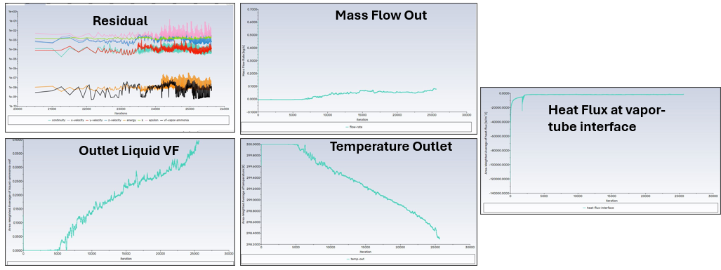
The simulation is giving negative value of heat flux at vapor-tube interface which means domain is releasing heat to tube wall. and heat transfer coefficient is positive so i think the direction for simulation is ok now.
what do you think?
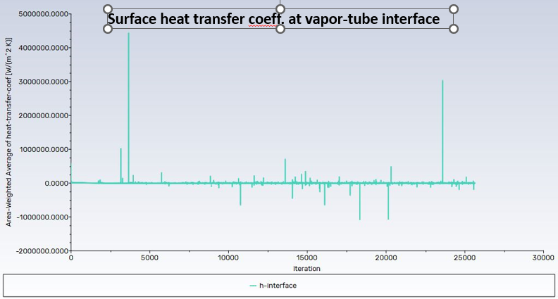
secondly, if you see the below residuals, vapor are condensing and temperature is droping so everything seems straight but the heat transfer coefficient (surface integral>area weighted avg > surface heat transfer coefficient) at the interface has some abnormal residuals. you can check below. why is that happening. if other things are ok, should i neglect it?
The calculation has run for around 0.12 s.
-
August 6, 2024 at 9:02 am
Rob
Forum ModeratorThe surface HTC will suffer where you have phase change, so use some care. Also check, I think the boundary flux is relative to 298.15K and is hard coded. Don't use CFD Post, and always check the volume fraction when reporting velocity - if there's a 0.00001 VF you'll still see a velocity which is physically meaningless.
-
August 7, 2024 at 9:55 am
abdullahhassan
SubscriberThankyou Sir,
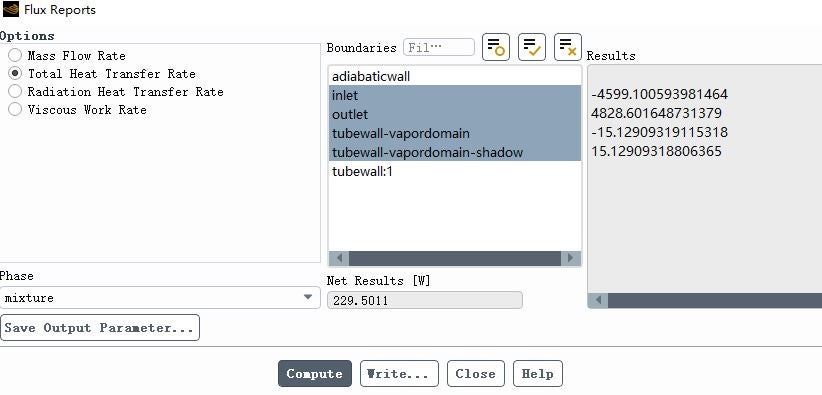
Can you guide me on about checking energy balance as well. As you can see in below image,
if I choose all boundaries then net heat transfer rate = -354W but if I skip either of Vapordomain_tubewall OR Tubewall:1 then the net heat transfer rate = 3W.
The confusion is, I have inputted constant temperature at tubewall:1 BC to accomodate water side heat flux and choose vapordomain_tubewall(interface) as Coupled.
If we see the net heat transfer rate then both have nearly same -351W of heat transfer rate.
Should I skip one boundary say tubewall:1? as we can consider both as same thing? I mean, the whole energy absorbed by interface will go to tubewall:1?
-
August 7, 2024 at 10:07 am
Rob
Forum ModeratorThe flux over the wall & shadow pair should be zero unless you altered anything: ie heat goes in one side and out the other. So, the sum of inlet, outlet and tubewall:1 should be near enough zero; if it's 3W then review the convergence guidelines in the training materials in Learning.
-
August 8, 2024 at 5:33 pm
abdullahhassan
SubscriberThankyou so much Sir. I learned alot while communicating with you in this thread.
I have a last question.
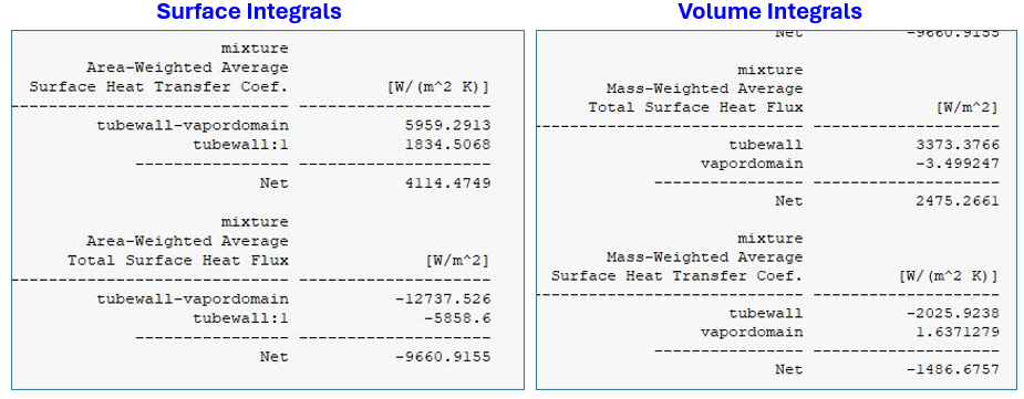
As you know, I have defined Heat flux (-5858W/m2) value at tubewall:1 (heat flux tube fluid should absorb). And by changing temperature at reference values tab, I am also able to achieve heat transfer coefficient(+ve) and heat flux (-ve) at boundaries in vapor domain.
but when I checked volume integrals, the heat flux at the tube wall is +ve and heat transfer coefficient due to heat flux becomes negative.1- why tubewall:1 & tube wall in both surface & volume integrals have opposite signs.
2- why -5858W/m2 is not reflecting at volume integral > tube wall ?
Is there anyway, I can calculate or understand heat flux calculations or what properties are really effecting it like for heat transfer coefficinet it is heff = q/Twall - Tref.
-
August 9, 2024 at 9:03 am
Rob
Forum ModeratorUse the Fluxes option in the Results panel. The surface integrals are using some averaging schemes so you need to understand the underlying maths.
The HTC is defined in the User's Guide, and is a function of reference temperature. Hence HTC can be pretty much any value you want based on the reference.
-
August 12, 2024 at 7:16 am
abdullahhassan
SubscriberI understood about HTC, but one thing is that if I calculate HTC theoretically and if I calculate using ANSYS, the values for both are really different. It maybe because ansys is using reference temperature and different heat flux to calculate.
Same is the thing with heat flux as my theoretical calculations based on books formula and ansys values are quite different.Is it possible to add these HTC and heat flux formulas using custom field functions inside ansys at this stage when almost the solution is stable enough and run the simulation for some more iterations so that ansys calculates HTC & heat flux at our formulas?
-
August 12, 2024 at 8:46 am
Rob
Forum ModeratorYou've got it - the reference values are nearly always a problem. The other issue is the "other" temperature used in literature/correlations as opposed to the Fluent model. There's even the lack of the solid conduction effects in some cases: you're reporting a h value but possibly comparing with U.
CFF's can be used, the issue can be how to get the various temperatures into the equation as they're done on a cell basis. Expressions may work as you can return area average values and use (some) local values. The "best" approach is often to extract raw data from Fluent (flux, temperature etc) and use a spreadsheet or similar: that way you control the refrence values.
-
August 12, 2024 at 4:05 pm
abdullahhassan
SubscriberYes, I tried to export the data previously using two methods
1- Making report defination for temperature etc and later exporting that data in excel. (the issue is, the data only comes with reference to timestep, flowtime or iterations.
2- Exporting the date using File > export > solution data > ACSII and exporting into excel. (The data comes with reference to Node Number).
What is the best possible way to export the data out of ansys + if I choose method 2 then should i first find out node numbers of Interface where i want to calculate heat flux etc and then average out heat flux on all the nodes of interface? -
August 13, 2024 at 7:14 am
abdullahhassan
SubscriberHi,
I exported ansys data using method 2 for only vapordomain_tubewall (interface) and then calculated the HTC and Heat transfer rate using correlations used by books and papers.
 and Q = hAdT.
 If we check below table, ANSYS fluent results are taken directly from Fluent Software.
Properties Theoretical HTC ANSYS Export ANSYS Fluent Results HTC 6518 7697 1514 Heat Transfer Rate 3295 1984 351 Note: All ANSYS Export values(density, K, viscosity) are averaged out by exporting only vapordomain_tubewall interface.
For (Tvapor - Twall); Twall = temperture we fixed at thermal BC and Tvapor = Export > vapor domain only > static temperature and then took area weighted average of it.
If we compare theoretical with ANSYS Export, the error lies within 20%, which is reasonable but there is a very big discrepancy between ANSYS exported data vs ANSYS calculates itself. My question is, is this normal discrepancy if we export data and calculates ourselves and also is the method to get the raw data is ok or not?
-
August 13, 2024 at 10:14 am
Rob
Forum ModeratorI would expect Fluent to agree with it's own data, but that's assuming you calculated everything in the same way: ie did you use area average etc. Typically I'd use the flux (Flux Reports, not Surface Integrals) and not use HTC as it's reliant on too many coefficients.
-
August 19, 2024 at 11:15 am
abdullahhassan
SubscriberHello Sir,Yes if I use area weigted average then ANSYS Export results match with ANSYS fluent. but I only used Average values so the results come near to equations obtained from books.I want to ask you one question that i asked before.If all my residuals are performing normally but the residual of heat tranfer coefficient suffers Ups / Downs in shape of wick. why is that happening? One important thing is that with the creation of wick in "h", their is no effect or abnormality in the residuals of PHASES (area weighted avg) or heat flux or temperature.What would be the reason for these wick formation? How can I improve this situation? -
August 20, 2024 at 8:40 am
abdullahhassan
SubscriberHi Sir,
Is there any solution to this problem as well or should I ignore it if other residuals are moving fine.
My concern is, my point of focus is heat transfer coefficient and it is making wicks as shown in above image. -
August 20, 2024 at 9:09 am
Rob
Forum ModeratorGiven the HTC will be impacted by the local phase I'd expect all sorts of spikes as the solution changes. The above isn't a residual of HTC, it's the value of HTC, so I'd expect noise. I wouldn't expect values of the scale you're seeing though, so that needs to be investigated.
-
August 21, 2024 at 3:18 am
abdullahhassan
SubscriberThank you.
Now how can I investigate that what is the problem.
If I see the residuals or heat flux values as heff = Q/Tref-Twall then both are showing normal trend i.e. there are no spikes or abnormality or noise.I have also tried to reduce the time step size from 0.0008 to 0.0006s so that if there is some problem arising due to timestep, it should be resolved but the problem persists.
-
August 21, 2024 at 8:35 am
Rob
Forum ModeratorIt's a transient model, and looking at the Flux curve it's not levelled off yet. If you also monitor phase mass/fraction on the surface how does it look? Note LOOK, there are contour & vector plots available in Fluent for a reason; we typically use a mix of numerical, xy plot and images to figure out what's going on in the model.
-
- The topic ‘Volume Fraction too Low. How to Improve?’ is closed to new replies.


-
5094
-
1830
-
1387
-
1248
-
1021

© 2026 Copyright ANSYS, Inc. All rights reserved.

