

-
-
October 3, 2021 at 1:49 am
ha_nguyen3
SubscriberI want to study E-fields across the model when applying 42V at 200kHz to copper plates that are coated with insulator (e of 5,000). I'm using Ansys HFSS and have the following questions:
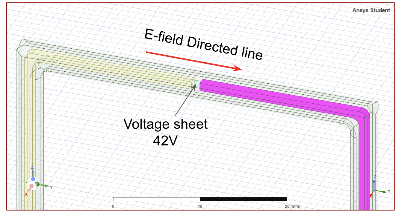
- To use "voltage" function as an excitation, I have to create a sheet. When the sheet is placed across the model to connect 2 conductors, it s the E-fields inside the model. I have to create "copper wires" that are extended from the copper plates and away from the model. The insulator also covers the extended portion. I create a sheet at the end of two "copper wires" to induce the voltage. Is it a correct way to use this "Voltage" function?
- The E-field in conductors should be 0. Instead of having "blue" color (0V/cm) on the bar scale, the conductors (yellow and purple) appear to be white. Does HFSS automatically exclude conductors from E-field display?
- The E-field in the air (e of 1) is 220V/cm while the E-field in the insulator (e of 5,000) is 0.2V/cm. I understand that due to higher dielectric constant, the E-field in insulators should be significantly lower than that in air. However, if the insulators completely cover the conductors, the E-fields are forced to travel across the insulators. Wouldn't the E-field in the insulators be higher than that in the air?
October 8, 2021 at 3:26 pmSubscriberPlease ignore the last question. I think what I meant here was E_polarization of the dielectric whereas Ansys displayed the net electric field. And it totally makes sense that E_net is lower for the dielectric compared to that for air.
October 11, 2021 at 7:40 pmSubscriberWould you please take a look at my questions? Please discard the last question.
"When the sheet is placed across the model to connect 2 conductors, it messes up the E-fields inside the model."
If you have any tutorials on how to use "voltage" as an excitation, I would really appreciate. I could only find videos for wave ports and lumped ports.
November 15, 2021 at 10:36 pmCB
Ansys Employeehave you tried using a circuit port? If I read into your question you just want to excite this device with some 50 ohm source impedance.
November 16, 2021 at 2:04 amSubscriber
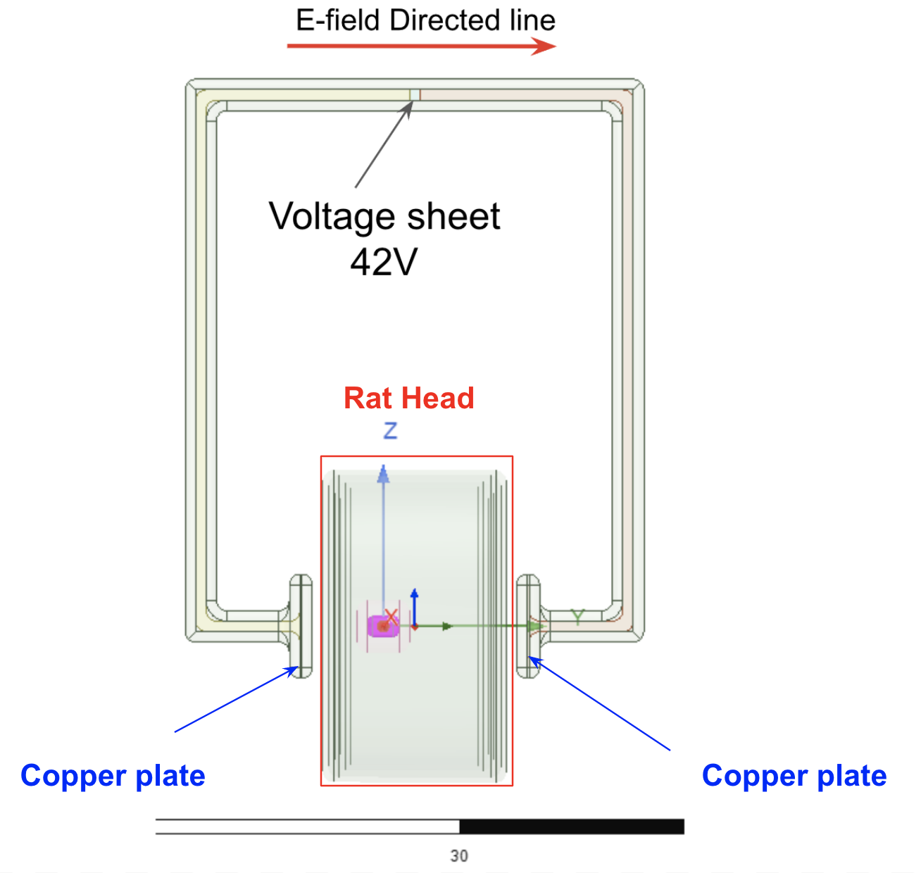
In brief, my model consists of a rat head (red box) that are placed between 2 copper plates (blue arrows). I want to study the E-fields in the rat head when applying 42V at 200kHz.
Initially, I tried to use lumped port as an excitation in my control model, but the results showed that the locations of the port affected the E-fields You can find the results in this post - /forum/discussion/31898/e-field-in-insulator#latest.
This problem occurred when using voltage source as well. To prevent the port or sheet cutting through or even touch the rat head, I created ÔÇ£extended wires" and connected them at the end (as shown below). This seems to give reasonable results for my study.
Regardless of using lumped port or voltage, what I try to do is to maintain the voltage difference between 2 copper plates at 42V and prevent unwanted effects of the port's placement on E-fields.
My questions are:
If this is an incorrect way to use voltage source, can you please let me know how this excitation should be done?
Would you kindly explain why you recommend a circuit port, instead of voltage source? And what is a circuit port that you prefer to? Do you mean wave port or lumped port?
I only know the applied voltage (42V) for my study. I don't know how much power or current it requires. If possible, I'm interested to learn how much power or current the copper plates consume.
November 16, 2021 at 2:07 amSubscriber
November 19, 2021 at 5:18 pmSubscriberThis question is closed on the Forum as models are being shared through Ansys Commercial Support Channel.
Viewing 6 reply threads- The topic ‘Voltage Excitation – Ansys HFSS’ is closed to new replies.
Ansys Innovation Space Trending discussions
- Y wiring method and the start and end points of winding.
- Lumped Port Deembed
- Hfss 3D pcb via capped and filled with epoxy
- Optimizing Via Impedance in Ansys HFSS 3D Layout Using Geometric Parameter Sweep
- AEDT Natural Convection with default correlation is failing solver initializatio
- HFSS libnvidia-ml.so too old or could not be found – Warning in slurm job output
- Three-Phase Voltage Imbalances in dual stator electric generator
- STL Import Errors in HFSS After Cleaning in SpaceClaim
- Calc Error in Field Calculator after PyAEDT Analyze
- import file autocad 3d
Top Contributors
-
peteroznewman
 3862
3862 -
scabo
 1414
1414 -
Dennis Chen
 1220
1220 -
javat33489
 1118
1118 -
Shyam Prasad V Atri
1015
Top Rated Tags
© 2025 Copyright ANSYS, Inc. All rights reserved.
Ansys does not support the usage of unauthorized Ansys software. Please visit www.ansys.com to obtain an official distribution.
-


The Ansys Learning Forum is a public forum. You are prohibited from providing (i) information that is confidential to You, your employer, or any third party, (ii) Personal Data or individually identifiable health information, (iii) any information that is U.S. Government Classified, Controlled Unclassified Information, International Traffic in Arms Regulators (ITAR) or Export Administration Regulators (EAR) controlled or otherwise have been determined by the United States Government or by a foreign government to require protection against unauthorized disclosure for reasons of national security, or (iv) topics or information restricted by the People's Republic of China data protection and privacy laws.


