-
-
October 31, 2023 at 4:56 am
Altair45
SubscriberGood day,
I'd like to verify the transmitted power in an index profile (n1,n2,n1,n2,n1,n2...) for a 3D FDTD simulation, comparing the results between the 3D FDTD and Transfer Matrix Method.Is there anyone who has experience with a 3D FDTD verification from a Transfer Matrix Method?
I would be grateful if you could help me.
Thank you
-
October 31, 2023 at 5:41 pm
Amrita Pati
Ansys EmployeeHi,
I have used 2D FDTD in the past to verify results from the Transfer Matrix Approcah. You can post your questions and I will try and help as much as I can.
Regards,
Amrita -
November 1, 2023 at 12:57 pm
Altair45
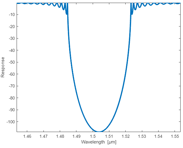
SubscriberHi,Thank you for your interest.I'm currently comparing the two data for Bragg grating instead of the index profile. I have set both parameters Period of grating and number of grating, same.But it is quite different from the little shift of center wavelength and range of reflection, as I attached TMM and 3D FDTD Graph.TMM Graph is the first one and 3D Graph is the second one.Can you advise about the reasons for this difference?I think the transmission of the 3D FDTD and TMM are different. aren't it?I'm also trying to compare the job to the index profiles, which is less complex than the Bragg grating.As your experience of verifying the 2D FDTD and TMM, Can you inform some matters that require attention in comparing between transmission of 2D FDTD and TMM? -
November 1, 2023 at 8:29 pm
Amrita Pati
Ansys EmployeeHi,
Thanks for sharing more information! It could be a number of reasons, we can take a look at various things one by one to see if we can get better agreement. I don't think we have to have any separate considerations while comparing the FDTD and TMM results. If you trust the TMM results, we just have to make sure that the FDTD results are accurate. I will start with some simple suggestions, you can test them, and then if there is no improvement we can go into more details.
- Status of the simulation: There are some ripples (near the minima) which I don't think is expected. Ripples in most cases are indicative of the simulation not having reached the auto shutoff level. After you run the simulation, click on the FDTD object, in the Results View Tab (below the Objects Tree section), you should be able to see a result called "Status". After the run the status should be 2. If it is 1, that means the simulation hasn't had enough time to reach the auto shutoff. So, increase the simulation time (maybe around 10 times) and then rerun it see if there is any improvement in the ripples. If the status is already 2, reduce the auto shutoff level to 1e-07 from 1e-05 in the Advanced options tab of FDTD object and run again.
- Also, for FDTD are you using dispersive material or a fixed index? Make sure that this is consistent with what you are doing in TMM. And if you are using dispersive material, check the fit in FDTD, make sure that the values of indices used by the model are close to what has been used in TMM.
Let me know what happens after you make these changes.
Regards,
Amrita -
November 2, 2023 at 5:38 am
Altair45
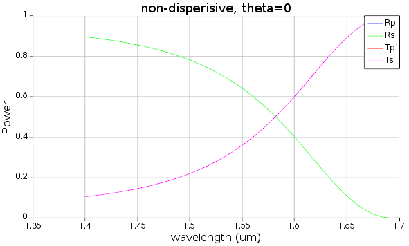
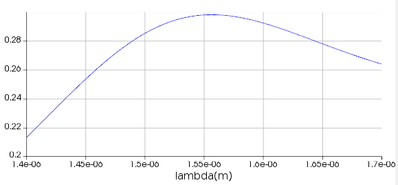
SubscriberGood for your advice!As you advised the setting of the simulation time, there was a status 1, so I reset the simulation time and waited for the results.On the other hand, I compared two graphs from the 10 index profiles consisting of the Si/SiO2 like the below script.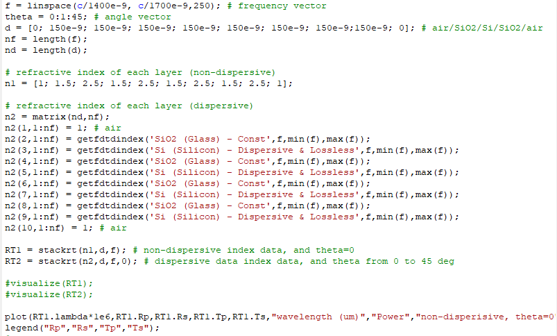 In terms of the non-dispersive index data, I created Si and SiO2 with 2.5 and 1.5, respectively in the material database. I constructed the object corresponding to the setting of the length of layers and located the mode source and transmission monitor at the entry point and end of the index profiles (Si/SiO2). But, two means show the different transmitted power like the below two graphs (script data and FDTD data).
 -
November 2, 2023 at 6:47 am
Altair45
SubscriberI checked that there is a mistake in setting the y point of the mode source. So, I result in similar tendencies between the two graphs. However, the 3D FDTD data is still lower than the TMM result as like below the two graphs.
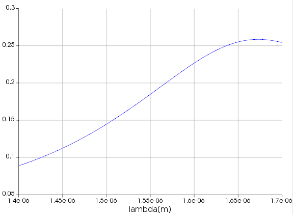
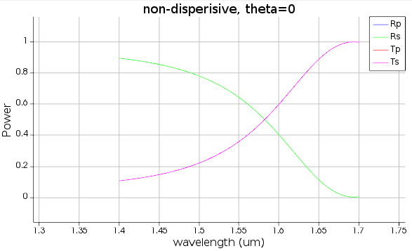
Are there any missed points like boundaries or FDTD settings as I attached the YZ view of the object? -
November 3, 2023 at 9:17 pm
Amrita Pati
Ansys EmployeeHi,
Would you be share a screenshot of the model? And the Boundary Conditions tab and Geometry Tab of the FDTD region?
Regards,
Amrita
-
- The topic ‘verifying the 3D FDTD simuation versus the Transfer Matrix Method’ is closed to new replies.


-
4673
-
1565
-
1386
-
1231
-
1021

© 2025 Copyright ANSYS, Inc. All rights reserved.

