TAGGED: nonlinear-analysis, transient-structural
-
-
February 25, 2024 at 11:38 am
Vincent Doan
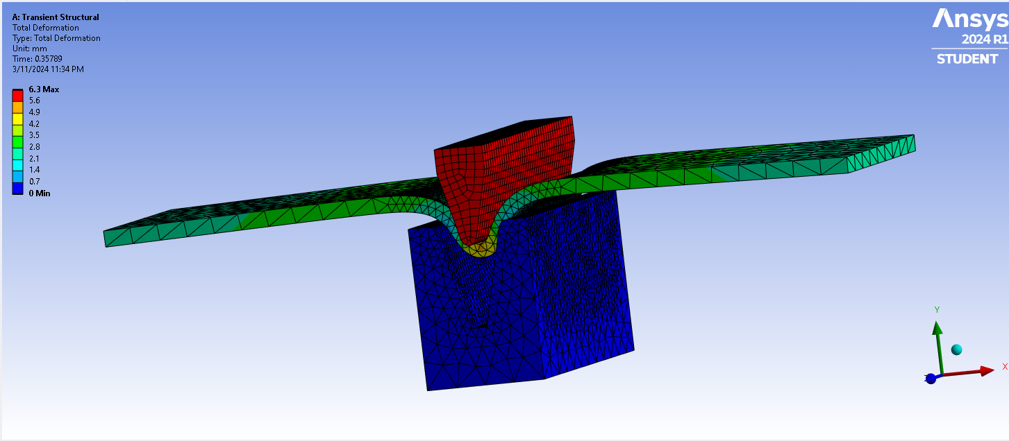
SubscriberI'm having trouble about the contacting in a V-bending process. I simulated successful for the 90 degree angle die, but when i change the angle to 30 degree, the punch keep passing through the metal sheet even though all my setting was the same as before.
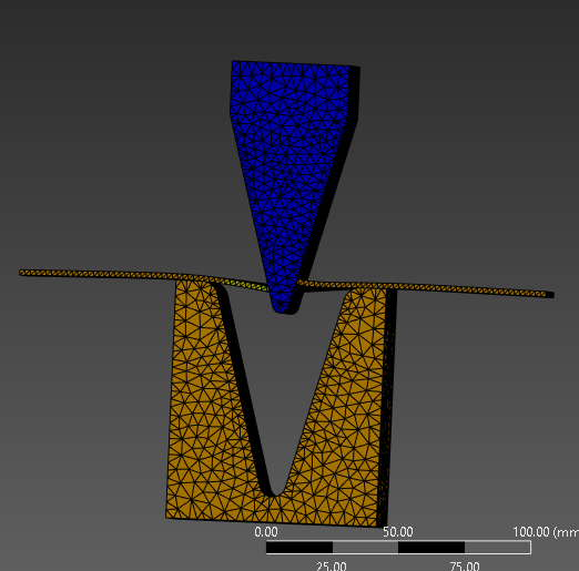
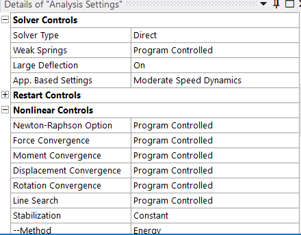
The image below is my contacts' setting.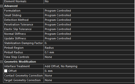
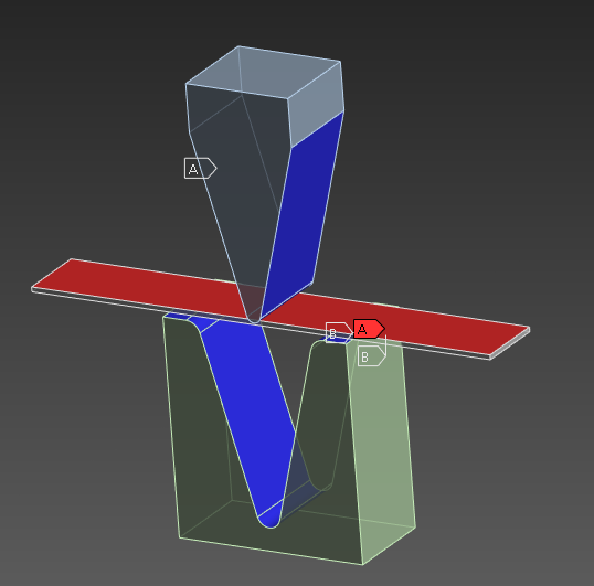
I'm looking forward to hear your suggestions. Thank you -
February 25, 2024 at 2:40 pm
peteroznewman
Subscriber/forum/forums/topic/sheet-metal-bending-static-structural/
/forum/forums/topic/problem-with-flex-sheet/
Suggestions:
- Use Static Structural, don't use Transient.
- Use 1/2 Symmetry instead of a full model.
- Use 2D Plane Strain instead of a 3D analysis.
-
March 11, 2024 at 4:40 pm
Vincent Doan
Subscriber
-
March 12, 2024 at 10:53 am
peteroznewman
SubscriberStabilization may be the cause of this problem. Plot the Stabilization Energy, and the Strain Energy in a chart to see if your model has excessive Stabilization Energy. You will not need Stabilization if you follow these suggestions for a 3D model:
- Use Static Structural, don't use Transient.
- Use 1/2 Symmetry instead of a full model.
- Change the punch and die to Rigid Bodies
The model will be easier and faster to solve if you use a 2D Plane Strain model.
-
March 12, 2024 at 1:11 pm
Vincent Doan
Subscriber1. Can Static Structural simulate the springback effect of the sheet metal plate?
2. Is the mesh have anything to do with this issue? Should i use hex mesh or tet mesh for better result?
3. I tried a 2D plane strain model on the XY plane, but when i try to solve it, the mesh crash
I hope you can help me with the above questions. Thank you!
-
March 13, 2024 at 1:27 am
peteroznewman
Subscriber- Static Structural can simulate the springback effect when you use a 2 step solution. Step 1 move the punch down. Step 2 move the punch up.
- Yes, you need at least 4 hex elements through the thickness. This is why it is so advantageous to do the problem in 2D plane strain.
- Show the error you had for the plane strain model.
-
March 13, 2024 at 7:35 am
Vincent Doan
SubscriberThis is what happening with my 2D plain strain model using Static Structural.
The error was: "Solver pivot warnings or errors have been encountered during the solution. This is usually a result of an ill conditioned matrix possibly due to unreasonable material properties, an under constrained model, or contact related issues. Check results carefully."
How can i resolve this issue?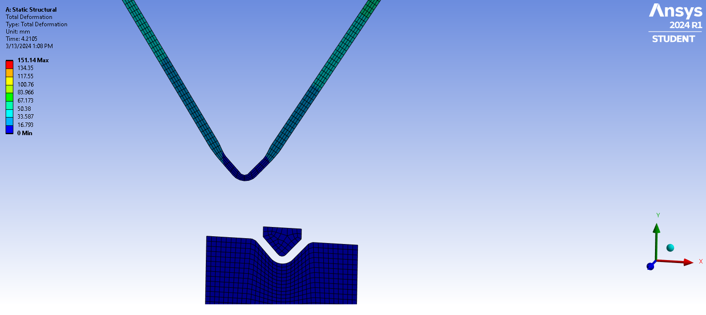
-
March 13, 2024 at 7:39 am
-
March 13, 2024 at 9:28 am
peteroznewman
SubscriberCut the geometry in half along the Y axis and delete the three pieces on the -X side. Apply a Displacement boundary condition of X = 0 to those edges. This will help control the sheet metal part.
Under analysis Settings, use a large number of substeps, say 100, for Initial, Minimum Substeps and a very large number of substeps for Maximum like 1000.
-
March 13, 2024 at 10:41 am
Vincent Doan
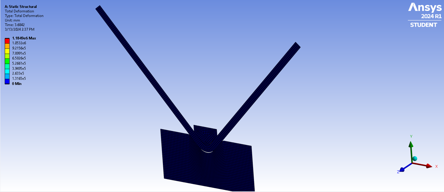
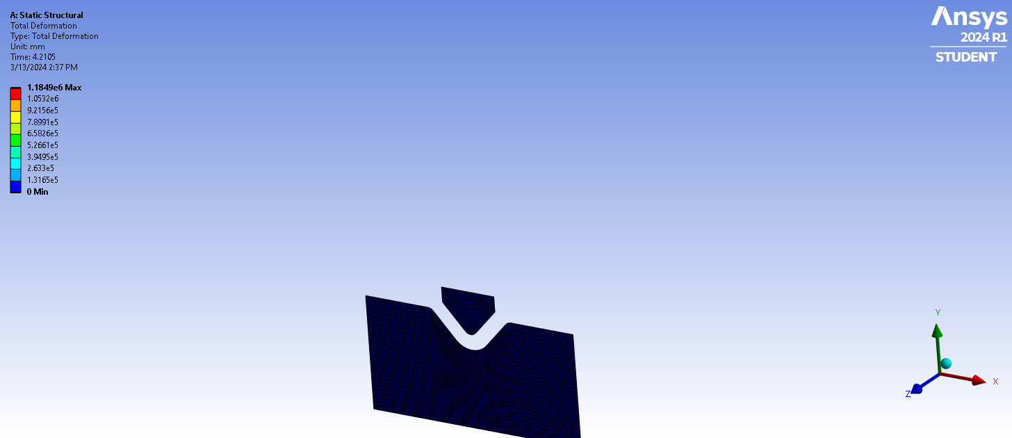
SubscriberI tried what you suggested, but I can't still simulate the springback process of the metal sheet plate. The plate got a little bit flatted down like the attach image
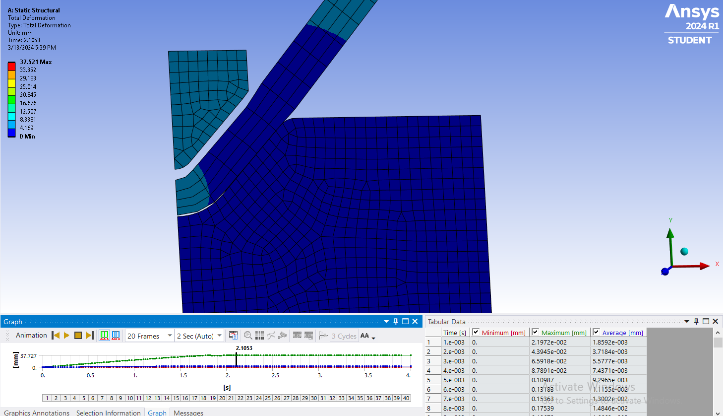
The above image I used Normal Lagrance, but when i tried to use other type of formulation, it still shows this error: "Solver pivot warnings or errors have been encountered during the solution. This is usually a result of an ill conditioned matrix possibly due to unreasonable material properties, an under constrained model, or contact related issues. Check results carefully."-
March 14, 2024 at 1:44 am
peteroznewman
SubscriberYou will see more springback if you have a shallower Vee-shaped punch and die. You will see more springback if you have a plasticity material model with a larger Tangent Modulus. You will more accurately model the springback if you have smaller elements. Make the element shape closer to a square and put 8 elements through the thickness.
-
March 14, 2024 at 3:25 am
Vincent Doan
Subscriber"Solver pivot warnings or errors have been encountered during the solution. This is usually a result of an ill conditioned matrix possibly due to unreasonable material properties, an under constrained model, or contact related issues. Check results carefully."
How can I resolve this issue for my model? I'm sure that my material is correct. My constraints were
- Fixed support: The bottom edge of die
- Displacement: Top edge of the punch ( x = 0, y = tabular ) -
March 14, 2024 at 6:42 pm
peteroznewman
SubscriberIt's not the punch or die, it is the plate. In a 2D plane strain analysis with a plane of symmetry on the Y axis (X = 0), the plate is free to move along the Y axis. When the punch lifts up past the springback point, the plate has no load on it.
Try turning on Standard Earth Gravity (-Y) to keep the plate sitting in the punch after the die retracts.
-
March 15, 2024 at 10:09 am
-
March 16, 2024 at 1:12 am
peteroznewman
SubscriberUnder Analysis Settings, set the Initial and Minimum Substeps to 100 and the Maximum Substeps to 1000 for each step and see if that helps.
Show the Newton Raphson Force Convergence Plot so we can see when the error occurs.
-
March 16, 2024 at 7:55 am
Vincent Doan
SubscriberMy professor advised me to use Transient Structural instead because he said that static structural analysis assumes that the loads and boundary conditions are constant and do not vary with time.
Do you have any suggestion for me to simulate this process using Transient Structural sir? -
March 16, 2024 at 1:37 pm
peteroznewman
SubscriberPoint out to the professor that the displacement boundary condition on the punch is changing with time. The main difference between Static and Transient Structural is that inertia forces are included in the latter. Since the punch and plate are moving slowly, the inertia forces are insignificant.
Did you try the substeps I suggested in my last reply? Where is the plot I suggested you show?
Though there is no need to use Transient Structural for this model, in Workbench, you can simply right click on the Static Structural block and change it to be Transient Structural.
-
March 16, 2024 at 4:03 pm
-
March 16, 2024 at 10:13 pm
peteroznewman
SubscriberGo back to using a Symmetry Plane and a Displacement BC on the Y axis (X = 0) in the Plane Strain analysis.
On the Mesh branch of the tree, for the row labelled Element Order, change it to Linear. Then on the Element Size, change it to a number that is 1/3 of the current size, so you get 12 elements through the thickness and 3 times more elements along the length. That will help with the bending.
You might have to add a third step. You need to have two separate Contacts, one for the Plate and Die and a separate one for the Punch and Plate. Set the End Time for Step 2 to be just before the Punch tries to separate from the Plate just before the convergence difficulty occurs. Then in Step 3, use Contact Step Control and Disable the Punch and Plate contact. Use a large number of Initial and Minimum Substeps for all thee steps.
This discussion shows a working model: /forum/forums/topic/problem-with-flex-sheet/
-
March 17, 2024 at 3:43 am
Vincent Doan
SubscriberI've also tried what you said and the result is still not that much better. I hope you can take some time and have a look at my ANSYS FILE. Thank you.
-
March 18, 2024 at 7:21 pm
peteroznewman
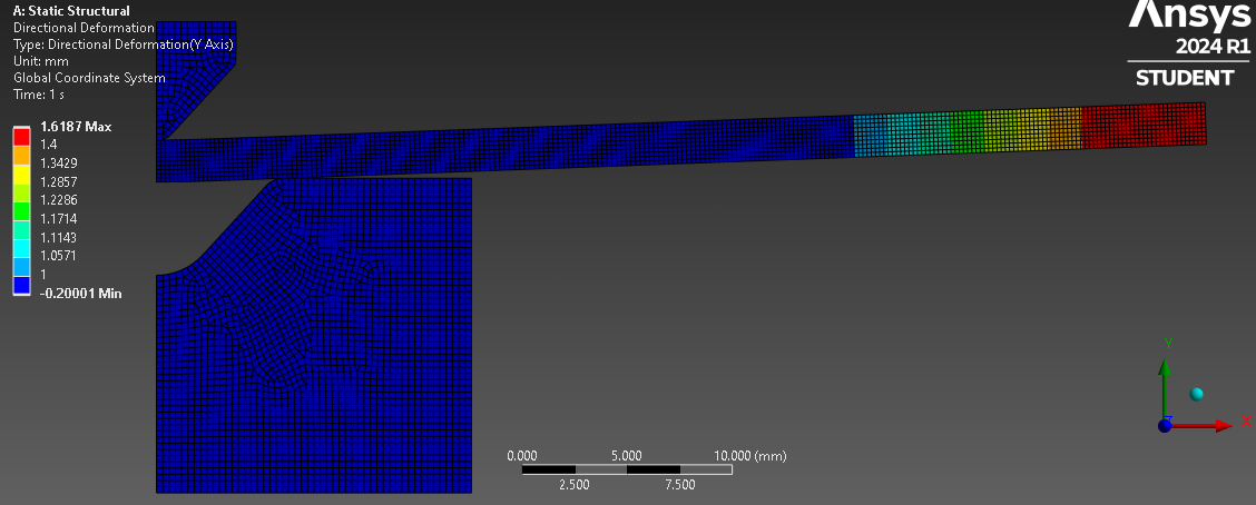
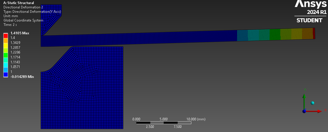
SubscriberI used the archive you provided. Make it a 2-step solution. Have the remote displacement at 1 second set to Y = -0.2 mm and the remote displacement set to Y = 0.0 mm at 2 seconds. Look at the free end of the plate. You will see a significant springback.
The reason you were not seeing much springback is because the bending was excessive and ended in lateral plastic flow as the entire section went into plastic strain with no elastic core to provide any springback.
-
March 21, 2024 at 3:05 pm
Vincent Doan
SubscriberHi,
Sorry for the late reply, I was busy with mid term so I have to put the simulation a side for a few days.
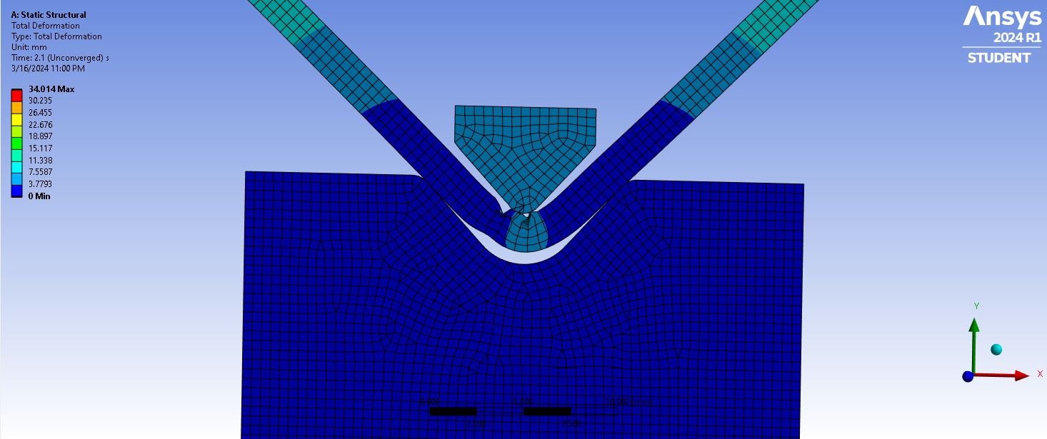
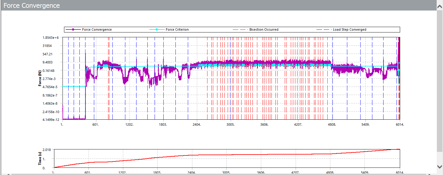
I managed to make the model worked in Transient 3D based on what you've pointed out earlier. But I've countered a small issue here. The solving process stopped without any specific error. It showed this warning: "The unconverged solution (identified as Substep 999999) is output for analysis debug purposes. Results at this time should not be used for any other purpose."
But when I look at my model, nothing is wrong with is. The mesh is normal, no unexpected high energy or penetration in the model.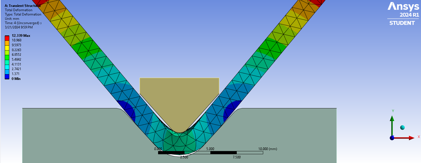
And here's the Force Convergence Graph. Everything's looking fine but it terminated the solution so sudden.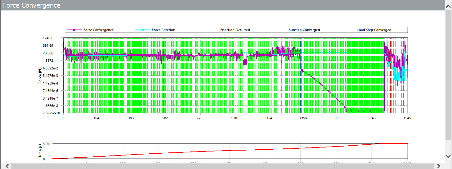
I hope you can help me solve this issue. Thank you. -
March 21, 2024 at 3:52 pm
peteroznewman
SubscriberLook at the Solution Output in the Solution Information folder. What do you see near the end of that file? Is there any error or does show that it could not converge. One reason Ansys can fail to converge is because the mesh is too coarse. Under Analysis Settings, type a number in for the Newton Raphson Force Residual plot to see which elements require smaller elements.
In general, your mesh should try to have at least 4 elements through the thickness. You only need small elements in the region being bent, so you could use a Sphere of Influence Sizing mesh control to make small elements in the bend area only.
-
-
-
March 13, 2024 at 11:34 am
ROHITH
SubscriberHEY PETER COULD JUST CHECK MY POSTS REGARDING " ROBOT FINGER ANALYSIS" I NEED YOUR HELP
-
- The topic ‘V-bending problem using Transient Structural’ is closed to new replies.


-
5094
-
1830
-
1387
-
1248
-
1021

© 2026 Copyright ANSYS, Inc. All rights reserved.

