TAGGED: ansys-icepak
-
-
August 31, 2023 at 12:55 am
Eric Steimle
SubscriberNow that I've figured out how to do a convection model I wanted to learn if I can somehow use the RthJSP which is the thermal resistance from LED wafer to the solder point under the package. This seems to be the common way LED manufactures specify their thermal properties. Anyway when I was asking the LED vendor for more information on the package material they suggested using the RthJSP in icepak somehow. Perhaps appling the 10 K/W RthJSP value to a point under the LED or on the PCB pad itself? Is there a way to specify this as a thermal source somehow or use it to connect the thermal source of the LED to the pad?
Thank you
-
September 1, 2023 at 2:37 pm
Rabindra Paul
Ansys EmployeeHi Eric:
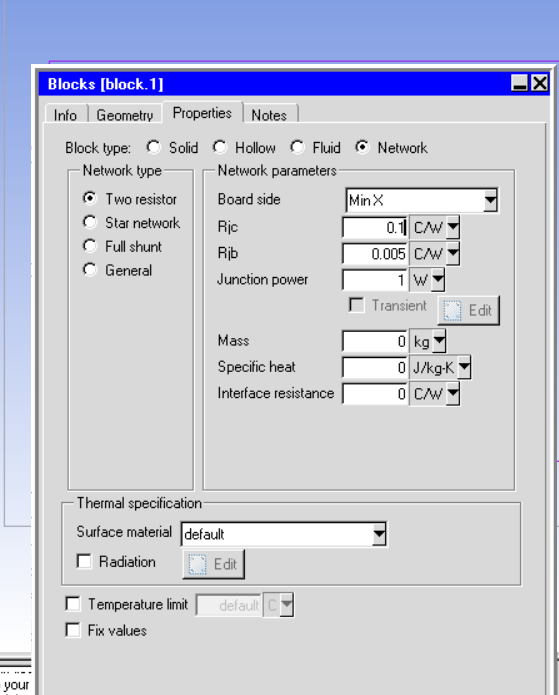
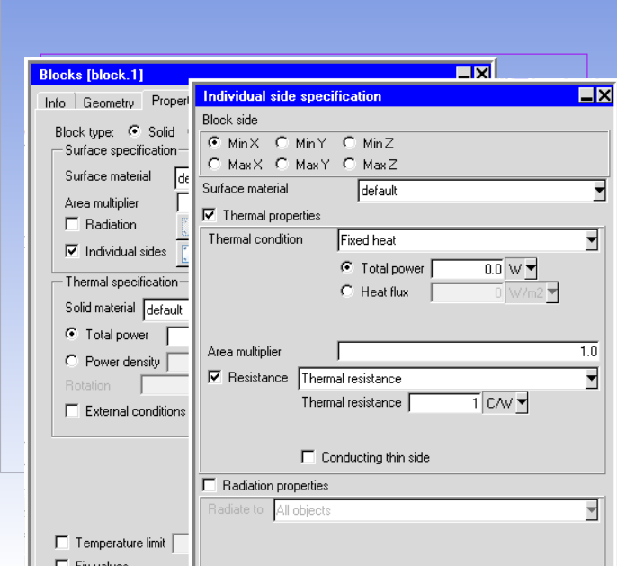
Thanks for contacting Forum. In Icepak network object can be used to simulate the complex object if the resistance values are known to define the heat transfer path. The simplest way to model heat transfer from a package is 2R network object, if user knows the resistance values for junction to case and junction to board. Another option is to use resistance from one side of the block is to use ' individual side' option and specify the additional resistance value. Attaching the images of the panels for both options below.
Please see document for details. Please let us know any comments.
Regards,
Rabindra
-
September 7, 2023 at 2:04 pm
Eric Steimle
SubscriberI'm having a little trouble trying this. I only have one Rth which is junction to solder point. The solderpoint is the pad on my PCB. So I tried to assign a network to the top face of that pad like so:
But I get this error when I try to simulate:
My network looks like this, and I set the thermal resistance of the link to my Rth and the power of the "internal" to my LED power. I don't understand the mesh error and didn't find anything searching the forums.
-
September 7, 2023 at 3:13 pm
Rabindra Paul
Ansys EmployeeEric,
Thanks for the note. As the error message says, the network face should have mesh on one side of the face. Typically, the network face must be on a hollow block or at the domain boundary. You might use resistance plate or individual side option or use 2 R network on a hollowblock (by allowing negligible heat in other direction by adjusting the resistance values). Hope this helps.
Regards,
Rabindra
-
September 7, 2023 at 3:48 pm
Eric Steimle
SubscriberI still don't quite understand sorry. How would I create a hollow block? All my imported geometry are solid blocks. I tried to use the block tool in icepak with a 2 r network by selecting the top and bottom face of the block. That gave me two Rs in the network setup but then complained about the double sided meshing again. Sorry, I'm having trouble understanding how to set this up. Even if I make a hollow block in CAD the inside will still have a face?
-
September 7, 2023 at 4:06 pm
Eric Steimle
Subscriberokay. I see you make a hollow object by deselecting the "solve internal" option for your object. So I tried that, assigned a 2R model to the top and bottom face of a pad and the simulation ran! Hurray, but when I try to generate temperature plots or generate a plot of the network temperature I get no output. compared to if I just assigned a thermal source here I'd see the temperatures.
-
September 7, 2023 at 8:34 pm
Rabindra Paul
Ansys EmployeeEric:
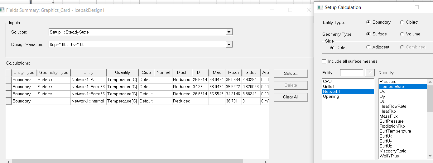
Yes, network, as no solution available within the block you can only get surface temperature on the network face. You can also report network junction tempertaure using field summary. Please review the document. If needed, please open a new thread for network postprocessing question. This will help us to classify the types of questions.
Regards,
Rabindra
-
- The topic ‘Using theta J (RthJA) in a icepak simulation’ is closed to new replies.


-
3767
-
1333
-
1173
-
1090
-
1014

© 2025 Copyright ANSYS, Inc. All rights reserved.


