-
-
November 23, 2023 at 3:37 pm
Marck Andersen
SubscriberHello
For my batchelor project I am doing a study on deep drawing a part in 4 steps. I have completed the first step to a level of satisfaction where I can bring the part of to the next step.
My question is how? The first step is done as a Static Structural study, and the following will be too.. how do i bring the result from the first study to the next maintaining all the residual internal stresses as they are of paramount importance to get a realistic result when I reach the last step.
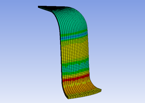
Above is an illustration of the first step result, and this is the only part I wish to bring on to the next study, while discarding the 3 shaping geometries used in the study.
I thank you in advance for your help.
-
November 23, 2023 at 8:53 pm
Ankush Choudhary
Ansys EmployeeHi Marck,
You can try using the INISTATE command, or you can also map stresses from your first analysis to the subsequent analysis.
/forum/forums/topic/inistate-command/
-
November 27, 2023 at 6:39 pm
Marck Andersen
SubscriberHi Ankush
Thank you very much, I'll look into that.
-
December 7, 2023 at 11:00 am
Marck Andersen
SubscriberI have come across an issue trying to import and map the nodal displacement onto the second step:
Thu Dec 07, 2023 11:15:04
Using multiple cores: [Yes]
Number of cores requested: 16
Maximum source mesh bounding box length: 0.135 (m)
Maximum range used in sorting closest nodes: 0.0108 (m)
Number of source nodes: 7380
Number of target nodes: 2824
Number of nodes mapped : 2824
Number of nodes not mapped : 0
Number of nodes outside : 0
Percent nodes mapped: 100%
Weight calculation time: 4.e-002 (s)
***************************************************ERROR***************************************************
File3:dX: Source nodes with undefined values were encountered during the interpolation process. Please check the source data.
***************************************************ERROR***************************************************
Number of variables to interpolate: 3.
Interpolation time: 0. (s)I am not sure what this means or where the number 7380 source nodes comes from, as there is only 2824 nodes in the file, all of which map perfectly.
The mesh of the part in question is the same in both studies, and is located the same place. Stresses and strains map without any issue.
Can anyone provide any help here?
-
- The topic ‘Use simulation result in subsequent study’ is closed to new replies.


- LPBF Simulation of dissimilar materials in ANSYS mechanical (Thermal Transient)
- Real Life Example of a non-symmetric eigenvalue problem
- How can the results of Pressures and Motions for all elements be obtained?
- BackGround Color
- Contact stiffness too big
- Element Birth and Death
- Python-Script to Export all Children of a Solution Tree
- Which equations and in what form are valid for defining excitations?

-
4597
-
1495
-
1386
-
1209
-
1021

© 2025 Copyright ANSYS, Inc. All rights reserved.


