TAGGED: hfss
-
-
August 2, 2021 at 2:38 pm
asadic
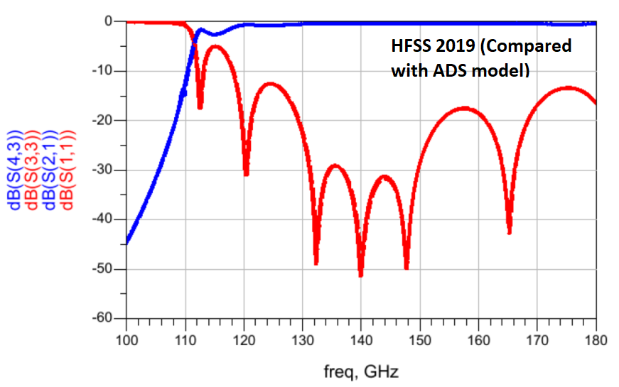
SubscriberI am running simulation for a simple rectangular waveguide (width: 438 um, Height: 100 um, Length: 1950 um, filled with insulator with dielectric contact of 9.7) using HFSS 2021R1.1 on Linux, but the results are surprisingly noisy and wrong! I simulated exactly the same model with the same simulation settings previously using HFSS 2019 on Linux and it was OK and perfectly matched with ADS model. I have attached the S parameters plot for you to compare. I was wondering if you could help me with this case. Thank you!
August 3, 2021 at 2:23 amAndyJP
Subscribercan you share the project file for checking please? I am concerned by simulations not fitting experiment well lately (which I attribute to the lack of data on materials), need to check this.
August 3, 2021 at 2:27 amAndyJP
SubscriberP.S.
Why did you call "simple rectangular waveguide" a "SIW-RWG equivalent"? Lets not include complex components like SIW into the basic performance test.
August 3, 2021 at 2:56 amasadic
SubscriberThank you for your prompt response. Attached is the HFSS file of the model.
I called it so because it is equivalent of the SIW model I am working on. For now, it is just a simple rectangular waveguide.
August 3, 2021 at 1:07 pmPraneeth
Ansys Employee
By looking at the result, it looks like the solution is not converged. Please check once.
You can also look at the SIW for 5G application example to check your simulation setup.
All the very best.
August 3, 2021 at 6:13 pmasadic
Subscriber
Thank you for your comment; but that is not convergence issue. As I mentioned above, I ran this model with exactly same settings (delta S, Max # of pass, ...) with 2019 and got correct results. Would you or please run the model with 2021 R1.1 with all settings I made to see what you get? Thank you.
August 4, 2021 at 8:03 amAndyJP
SubscriberOk. please wait till tomorrow. I got an optimization running, no extra GUI license, and ANSYS lawyer sharks at my back claiming that I use more licenses than my workstation can consume. (I would start with CTS If I know ANSYS practices money extortion schemes)... I really do not believe it may get that different, but need to see that myself.
August 5, 2021 at 10:47 pmasadic
Subscriber
I was wondering if you had the chance to try this. Thank you.
August 6, 2021 at 3:04 amAndyJP
SubscriberOK. There was a link break between the license server, an the simulation could not recover (again, ANSYS does not fix its license server logics for decades, but keeps extorting money when something weird happens with licensing at their spy-door monitor)..
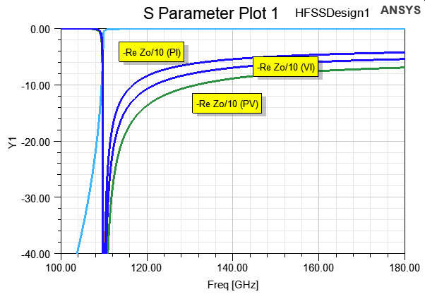
...So, I abandoned my sequence, and tried your file. I confirm the second image with 100% certainty.
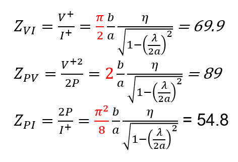
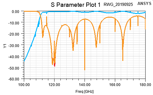 Speaking of port impedance setup, it is not correct for RWG, because the main countable values are for surface current, so you should set PI for RWG, and PV, or Wave for coplanar and other open waveguides. There was a discussion in the old manual, but it is hard to find in new HTML version.
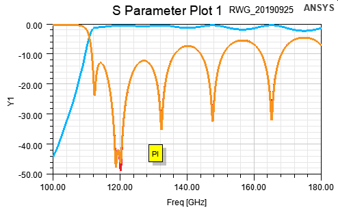 Now, you see how a small error influences te S-plot? And you have used impedance renormalization to 89 Ohm (you did not tell that). So why did you do that? Can you confirm that you've used the same renormalization in other cases?
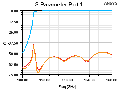
Here are non-renormalized direct WG to WG S-parameters.
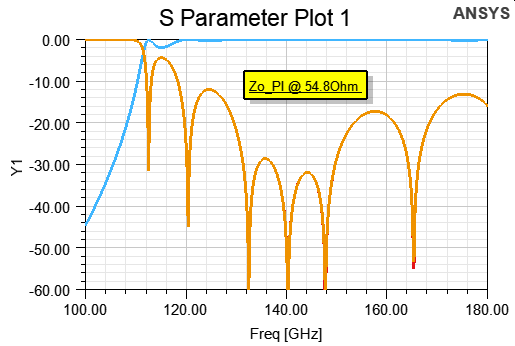
 Now, lets try fixing the reference impedance to Zo=54.8 Ohm (the waveguide impedance at 140MHz) , and viola!
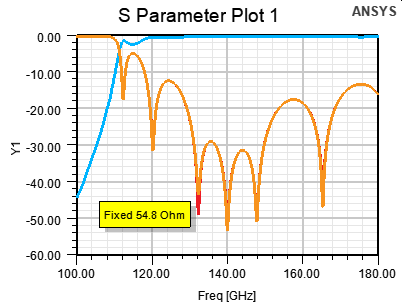 Did you look for that image?
Try using exactly the same project file as in the older HFSS version. Unfortunately, higher version files may fail loading to older HFSS. And I can not check the old version myself now since we shifted the licenses long ago.
August 6, 2021 at 3:11 amAndyJP
Subscriberfrom the manual:
Calculating Characteristic Impedance
Each port in a structure being analyzed can be viewed as a cross-section of a transmission line.
HFSS computes the characteristic impedance of each port in three ways ÔÇö as Zpi, Zpv, and Zvi
impedances. You have the option of specifying which impedance will be used in the renormaliza-
tion calculations.
ÔÇó For TEM waves, the Zvi impedance converges on the port's actual impedance and should be
used.
ÔÇó When modeling microstrips, it is sometimes more appropriate to use the Zpi impedance.
ÔÇó For slot-type structures (such as inline or coplanar waveguides), Zpv impedance is the most
appropriate.
HFSS will always calculate Zpi impedance, the im
August 6, 2021 at 3:55 amasadic
Subscriber
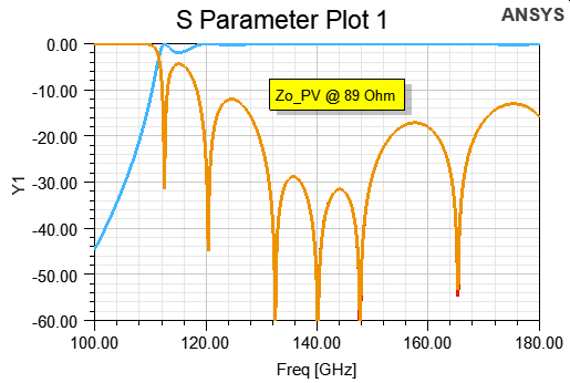
Thank you so much for looking into this issue. I used impedance renormalization to 54.8 Ohm for Zpi and got the correct results as you showed. Now question is that "why in version 2019 I could use impedance renormalization to 89 for Zpv and still got the correct results?" Just to clarify, please check the attached for impedance calculation of the model. As you can see Zpv is 89 ohm and Zpi is 54.8 ohm for this model. So, as I confirmed with HFSS 2019, I should get the same results by renormalizing the port impedance to 89 for Zpv. But, why that is not the case for this new version?!
August 6, 2021 at 5:11 amAndyJP
Subscriberwho is andyabrahao?
>"why in version 2019 I could use impedance renormalization to 89 for Zpv and still got the correct results?"
I don't think you did. Probably, you was not clicking the "enabled" Ôÿæ checkbox on.
That would be very interesting if you can confirm that v2019 actually gives different results. As I said, try executing the exactly the same project in 2019, then in 202x.
P.S. really, that is weird. All four impedances produce the same Zo(1) plot. I am confused since not longer than 2 months ago I was pointing out to someone that these impedances are different and are scaled relatively to each other. Not taking into account the difficulties of finite integration.
August 6, 2021 at 4:26 pmasadic
Subscriber"I don't think you did. Probably, you was not clicking the "enabled" Ôÿæ checkbox on."
I am actually 100% sure, and that something I have been doing that for more than a year during the design process and finally confirmed it with measurement as well. As I have shown in the plot, I did confirmed it with ADS model too, and they matched prefectly when I simulated ADS model with 89 ohm port impedance.
"As I said, try executing the exactly the same project in 2019, then in 202x."
I do not have access to 2019; but as I said above, previously, I did EXACTLY the same model with 2019 and with 89 ohm for Zpv and got the correct results for sure. There is no doubt for me about it.
August 9, 2021 at 8:21 pmasadic
Subscriber
Please check this model. I simulated it with HFSS 2019 before with Zpv of 50 ohm and compared the results with measurement.
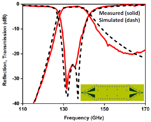
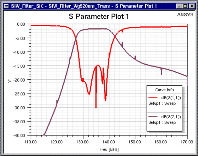
Now, I am simulating EXACTLY the same model with the same settings with HFSS 2021R1.1. I got following plot!
Per our previous discussion, I used Zpi of 50 ohm for that model, here is the results:
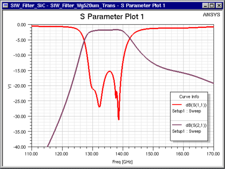
Something is really wrong. I cannot trust the results. You are welcome to try this model too. Attached is the HFSS file of this model.
August 10, 2021 at 12:26 amAndyJP
SubscriberWOW
seems like I am falling into the deep black void...
August 10, 2021 at 1:03 amAugust 10, 2021 at 1:24 amasadic
Subscriber
What you just show here is exactly what I expected and I used to get them with HFSS 2019. Which version did you used?
Just to be clear, I did not import the model; I also created the model again in 2021R1.1.
August 10, 2021 at 2:06 amAndyJP
Subscriber2021R1 (build 2020-11-16 21:49:12)
Created clear with NEW command. PEC walls, SiC made from Alumina with your dielectric parameters.
August 10, 2021 at 2:11 amAndyJP
SubscriberYour header:
$begin 'AnsoftProject'
Created='Wed Sep 25 14:49:34 2019'
Product='ElectronicsDesktop'
FileOwnedByWorkbench=false
$begin 'Desktop'
Version(2021, 1)
InfrastructureVersion(1, 0)
$begin 'FactoryHeader'
$end 'FactoryHeader'
$end 'Desktop'
My header:
$begin 'AnsoftProject'
Created='Tue Aug 10 08:39:00 2021'
Product='ElectronicsDesktop'
FileOwnedByWorkbench=false
$begin 'Desktop'
Version(2021, 1)
InfrastructureVersion(1, 0)
$begin 'FactoryHeader'
$end 'FactoryHeader'
$end 'Desktop'
UsesAdvancedFeatures=false
NextUniqueID=0
Probably, you've imported it from ver.2019 file than edited. In my case I used "NEW" command.
August 10, 2021 at 11:30 amasadic
Subscriber
As I mentioned before, I tried that with a new model created in 2021, still the same result. When you got that result I made a new model again and tried it. Here is the result with Zpv of 89 ohm:
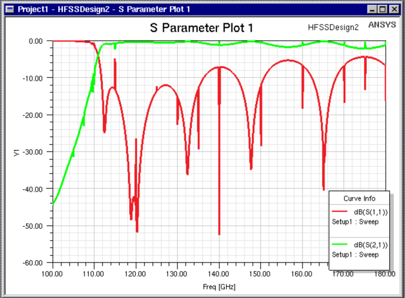 If you can get the correct results by 20121R1.1 similar to the one I got using 2019, why I can not?! Attached is the model I just created in and tried with 20121R1.1. Would you please import and try this one as well? I am really puzzled!
August 11, 2021 at 2:58 amAndyJP
SubscriberI can not calculate it right now, because I have quite a complex 3-days optimization script running; but don't you find these spikes suspicious?
More I look at them, more it looks like the spikes point at correct values, while other continuous sections represent something duplicated from the reference PI data.... Can you try overlapping them, in GIMP, or in PowerPoint maybe?
BTW, I forgot to tell you that I always use second order or mixed order simulation (because I always deal either with curves, or with sharp edges providing curved field profiles).
August 12, 2021 at 11:14 pmasadic
Subscriber
Are you running this on Windows or Linux?
August 12, 2021 at 11:30 pmAndyJP
SubscriberWindows. I have the same results as you with your files.
August 12, 2021 at 11:32 pmasadic
SubscriberExcellent. So, probably it means it is not fully compatible with Linux that I am running on!
August 17, 2021 at 12:43 pmAndyJP
SubscriberDid you try improving convergence? In may be a bug with badly converged results, because I do not see other explanation. Project files look pretty the same with minor differences in versions.
August 17, 2021 at 2:23 pmasadic
Subscriber
I believe mystery solved! Luckily, it was only a post-processing issue (apparently, just in Linux). Meaning the S parameters from simulations are accurate and highly reliable; but once we do normalization to the port impedance (Zpv = 89 ohm for example, as a post-processing step) the results do not make sense. What I do now is to simulate the model with Zpv defined without normalizing that. Then, once I want to export the S parameters, I do renormalization to 89 ohm. When I simulate the extracted S parameters in ADS with Zpv = 89 ohm, that perfectly matches with what I used to get from HFSS 2019.
So, I believe there is a bug (maybe just in Linux) in normalization in the part that ports are defined; otherwise, everything else seems OK.
August 23, 2021 at 8:04 amAndyJP
SubscriberAs I said, with your file I got the same in Windows. So you should submit the bug report to ANSYS through your vendor while it is hot; or the bug will haunt us for another decade.
Viewing 26 reply threads- The topic ‘Urgent!! – HFSS 2021R1.1 Wrong Results’ is closed to new replies.
Innovation SpaceTrending discussionsTop Contributors-
5094
-
1824
-
1387
-
1248
-
1021
Top Rated Tags© 2026 Copyright ANSYS, Inc. All rights reserved.
Ansys does not support the usage of unauthorized Ansys software. Please visit www.ansys.com to obtain an official distribution.
-
The Ansys Learning Forum is a public forum. You are prohibited from providing (i) information that is confidential to You, your employer, or any third party, (ii) Personal Data or individually identifiable health information, (iii) any information that is U.S. Government Classified, Controlled Unclassified Information, International Traffic in Arms Regulators (ITAR) or Export Administration Regulators (EAR) controlled or otherwise have been determined by the United States Government or by a foreign government to require protection against unauthorized disclosure for reasons of national security, or (iv) topics or information restricted by the People's Republic of China data protection and privacy laws.

