TAGGED: #hfss-#lumped_sources, question
-
-
January 14, 2025 at 4:29 am
ll886
SubscriberDear Ansys support team,
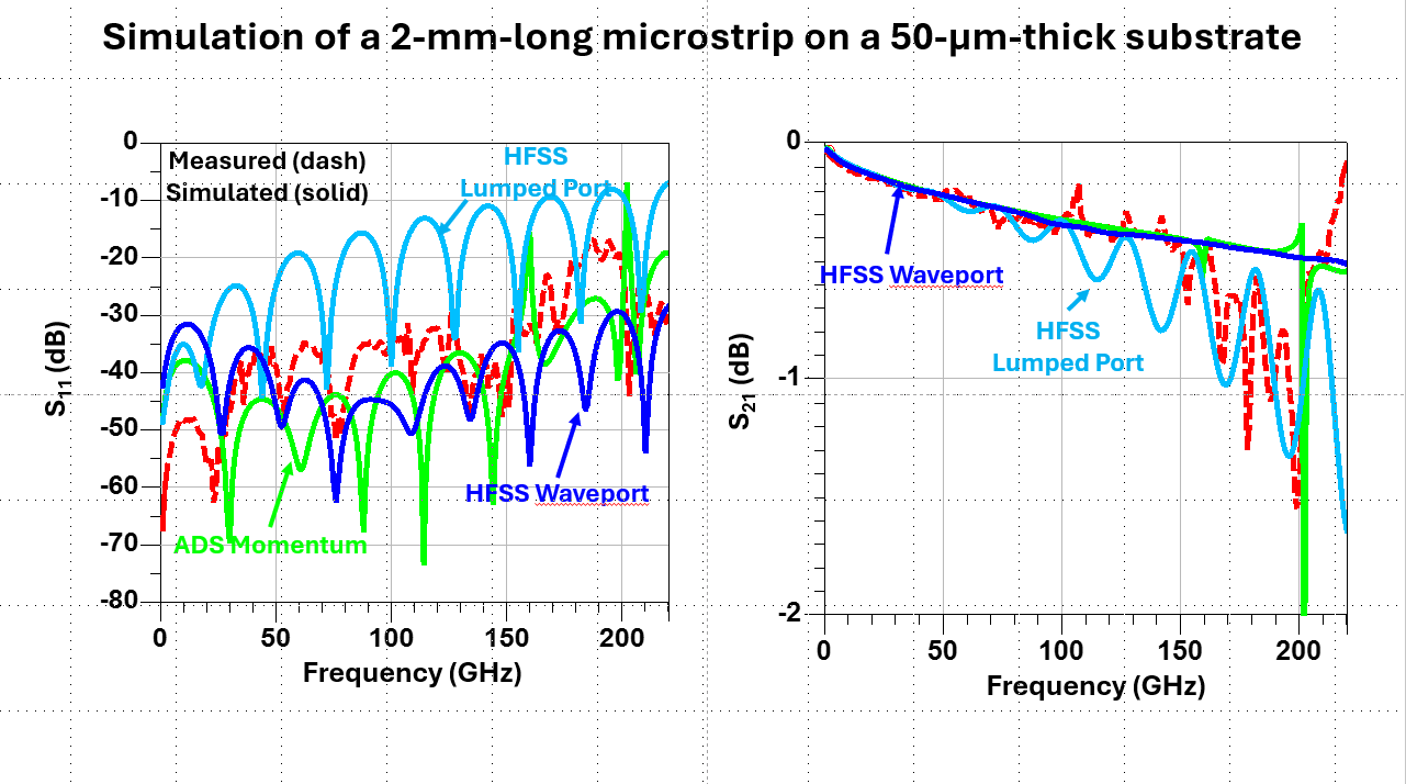
I am using HFSS to simulate a simple microstrip line to fit my measured data. I noticed that the one simulated by lumped port shows unresonable return loss ( thus the insertion loss) compared with the waveport, ADS momentum, or the measured data, as shown in the picture below. I suspect this happened because of the port de-embedding options in lumped ports of HFSS. I did a quick simulation using ADS components, which shows that by putting a shunt capacitor of 6 fF at the ports, ADS can explain the high return loss of the simulation using HFSS lumped port. Does this indicate the the lumped ports in HFSS are not properly de-embeded eventhough the "de-embed" option is selected? I wonder if you can help check the attached Ansys project to make sure my set up is correct? Also, I wonder, since in many cases we need lumped ports as internal ports, how can we use the lumped ports with confidence?
Note: Ansys HFSS version is 24R2 on Linux. Here is the google drive link for the HFSS project:https://drive.google.com/file/d/1wydOCVXxWRC8qCl9t6zl-hll5WZF0HVm/view?usp=sharing
Thank you!
-
January 14, 2025 at 4:39 am
ll886
Subscriber@Ansys Innovation Space Help
-
January 15, 2025 at 6:28 am
Gia
Ansys EmployeeHow big are your lumped ports? - They must be electrically small to provide valid results.
Another potential source of the difference in the results is that wave ports compute the Z0 of the port, while lumped ports assume a specified Z0.
Wave ports can be used internally if you place a volume of metal on the opposide side of the waveport (180deg opposite the direction of the launch). - This is sometimes refered to as a 'PEC Cap or Port Cap'. - Create a copy of the waveport sheet/face, use the 'Thicken Sheet' command to extrude it into the 3rd dimension approx. 1-2mm and then set the material of this new object as PEC.
-
January 15, 2025 at 6:55 am
ll886
SubscriberHi Gia,
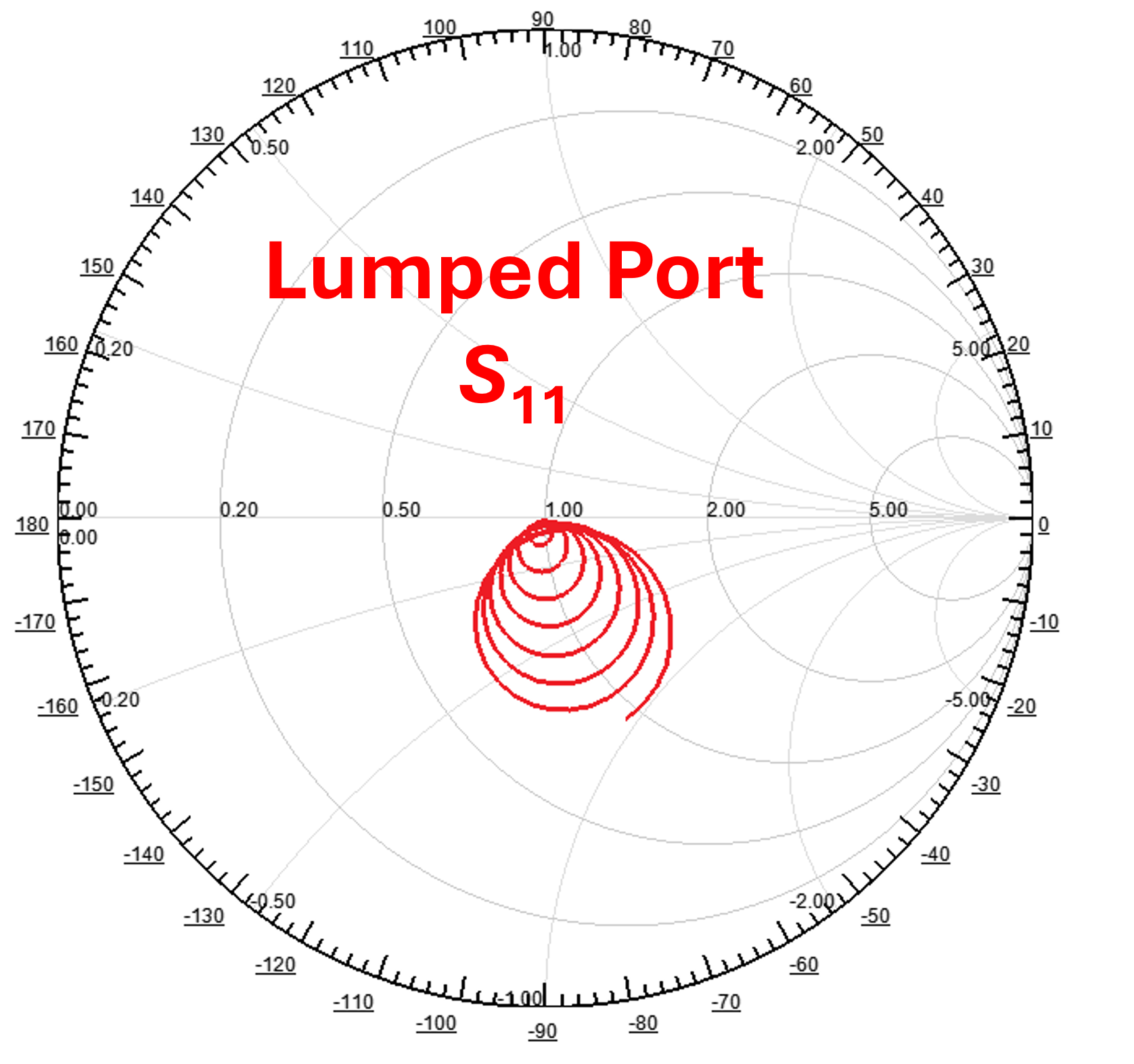
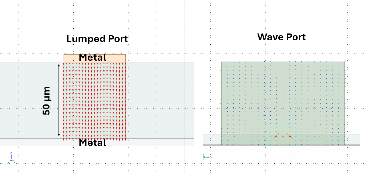
Thanks for your reply. The lumped ports size is 41-um by 50-um. At 140 GHz, the wavelength is around 1-mm. Is this too big? I already tried reducing the wdith of the lumped ports, but their effects are marginal. The microstrip in my deisgn is designed to be 50 ohm, confirmed by HFSS waveport, calculation, or measurement. So I don’t think the issue is caused by the port Z0. On the other hand, the smith chart of the lumped S11 as shwon below indicates there are capacitive parasitics associated to the ports and the de-embedding is not doing its works. Further, putting the waveport inside the model is not realistic in many cases, for example, MMIC design which requires internal ports to connect with transistors for circuits-EM cosimulation. The wave ports can be too big in such cases.
-
January 15, 2025 at 7:15 am
Gia
Ansys EmployeeThe lumped port assumes a homogenous field excitaion across the port face, which is only valid if the port length/width is < ~lambda/20.
Deembedding on lumped ports only removes parasitic inductance, not capacitance.
Have you tried Circuit Ports? - They act similar to lumped ports, but they are defined across two adjacent edges.
-
January 15, 2025 at 7:52 am
ll886
SubscriberHi Gia,
Yes, I tried circuit ports in both modal and terminal solutions. They gave similar results as the lumped ports.
-
- You must be logged in to reply to this topic.


-
5159
-
1836
-
1387
-
1249
-
1021

© 2026 Copyright ANSYS, Inc. All rights reserved.


