Photonics

Photonics

Topics related to Lumerical and more.

Updating a Lumerical example

    • sara.bassil
      Subscriber

      Hello,  I found this example in lumerical : https://optics.ansys.com/hc/en-us/articles/19435937674387-Thin-Film-Lithium-Niobate-Electro-Optic-Phase-Modulator  I am trying to change the gap between the electrodes of the example to see the impact on the losses and the Vpi but the results do not change and I can't understand why. Can you help me ?  Thank you, Best regards Sara 

    • kghaffari
      Ansys Employee

      Hi Sara, 

      Thank you for posting your question. Can you please share the inputs and results for each scenario? Specifically, please share the gap length you are simulating for each case (a simple schematic can be helpful too) and the loss/Vpi results for each case. I will then run the example with the same setting to reproduce and troubleshoot the issue you are having. Thank you.

      Khash

    • sara.bassil
      Subscriber

      Hi Khash, thank you for your answer,

      In the initial example, the gap between the electrodes is 5µm. I change it to 3µm keeping everything else the same. 

      And I have stricly the same performances :

      Thanks again for your help!

      Sara 

    • sara.bassil
      Subscriber

      Then, I replaced the quartz by Silicon ==> Same results 

      Then I removed the LN waveguide and kept only the slab ==> Same results 

      I feel like it always calculates the same electric field even though I am changing the gap inter electrodes. And when I remove the LN waveguide it should change the effective index but nothing happens 


    • kghaffari
      Ansys Employee

      Hi Sara,

      Thank you for your detailed information. I noticed that in this example the "lock mesh" option is enabled for both CHARGE and FEEM solvers. To check the status of this option you can right click on the solver:

      I think this is causing the issue. The lock mesh option will keep the mesh and settings that depend on it the same. This is particularly useful when running sweeps (which is done later in this example) to ensure that any changes are due to physical effects and not new generated mesh. However, it will also cause your design to not be updated. Please try disabling this option and try again. Let me know if the issue persists.

      Best,

      Khash


    • sara.bassil
      Subscriber

      Hello, yes you are right! I was able to change this and it works better, 

      Do you know how I can modify the code to do a sweep over the gap between the electrodes? Is it possible to implement such a sweep ? 

      Thank you for your help! 

      Sara 

    • sara.bassil
      Subscriber

      Another question : I want to remove the lithium niobate waveguide, keep the slab and put another Si or SiN waveguide below the LN slab.

      When I do that, the FEEM simulation doesn't found the mode, is there a way to force the simulation to give the mode that is between the LN and the Si waveguide ? 

      I feel like the simulation is searching for a mode in the lithium niobate waveguide and slab, is this true ? If it is, is there a way to change it ? Thank you!!

      Sara 

    • sara.bassil
      Subscriber

      Hello Khash

      I just wanted to let you know that I figured out my problem : 
      I run the simulation without the electrodes and I extract the effective index of the mode I want. I put back the electrodes and I run the simulation around that effective index and it works pretty nicely ! ;) 

      If however you have an idea on how to implement a sweep I am all ears

      Thanks again for your assistance 

      Sara 

    • kghaffari
      Ansys Employee

      Hi Sara,

      Thank you for the update. Great to hear the issue about finding the mode is resolved! 

      To answer your question about sweeping a parameter, this can be done by switching to the “Optimizations and Sweeps” tab (typically located on the right side of the UI) and then creating a new parameter sweep (as shown below):

      Once you create a new sweep, you can define the parameters of interest to be swept, and the results you are interested in to be monitored. Please refer to this article for a more detailed description on how to work with the sweep utility.

      The parameter you would like to sweep, may already be available in the list of objects. However, I suspect in your case the electrode gap is not a readily available parameter. You would have to define this parameter in the Objects Tree’s “model” object:

      Once you add the gap as a variable, you would have to use it in the script tab so the gap can be modified using this variable. I think this can be done by scripting the location or length of the electrodes to rely on this variable. The new parameter will be accessible in the sweep utility and can be swept to study its effect on the device performance.

      Best,

      Khash

    • sara.bassil
      Subscriber

      Hi again, 

      Thank you for your answer, I was actually trying to implement the sweep in the script. 

      My goal is to run charge and extract the electric field for each value of the gap. 
      I want to store the value of the electric field for each value of the gap in a matrix and use it outside of the loop to compute the perturbed index. 

      The issue I am encountering is regarding the electric field : 
      The matrix E that is generated in the script with these commands :
      electro = getresult("CHARGE::monitor","electrostatics");
      E = pinch(electro.E);}

      is different from the one I see when I go : monitor > electrostatics > E > view data 
      Is it because the simulation is using unstructured dataset ? 

      Anyhow, I have some issues understanding to what corresponds the 3rd size of the E matrix  :
      ?size(E);
      result: 
      23828  11  3 

      I assume that the first value is the x values ? 
      The second one corresponds to the voltage applied 
      And the third one .. I have no idea ? 


      Thank you again for your assistance!


    • sara.bassil
      Subscriber

      Hi again, I think you have responded to my question of december 12 but it doesn't appear on this feed :(

      Do you know why ? is this some bug of the website ? 

    • kghaffari
      Ansys Employee

      Hi Sara,

      I think I had saved a draft but I'm not sure if I did send my response. In any case, sorry for the delay.

      The third dimension corresponds to coordinates (x,y,z). The values here show where each data point (of E) is located at (at a given voltage). To extract the coordinates you can use few lines like:

      electro = getresult(“CHARGE::monitor”,”electrostatics”);

      x = electro.x;

      It seems that the data matrix shown by clicking on visualization’s “View Data” doesn’t include coordinates or its dimension. 

      I hope this is helpful. Please let me know if you have any follow up comments or questions.

      Best, Khash

    • sara.bassil
      Subscriber

      Thank you so much that helped !!

      I am first doing the sweep over the gap to extract the final E matrix (Ef) of dimension (length(datapoints), 3, length(gaps)) 
      However the datapoints don't have the same length for each gap 
      So I chose to cut the extra values : 
      For example if ?size(E) ; = (1450,3) 
      I did this : Ef(:,:,i)=E(1:1400,:)
      with Ef = matrix(1400,3,length(gaps))

      So once I have my final E matrix I do a sweep over the gap to compute the perturbed index. 
      However when I want to use the function addattribute I have this following error : matrix for addattribute does not have the correct size to match the dataset 

      I think it's because the dimension of my final E matrix is : (1400, 3, length(gaps)) and not (1400, length(gaps), 3) 
      Is there a way I can add the attribute to the electrosattics dataset ? 
      My next step is to use the FEEM script and modify it as well to obtain the Vpi and the losses in function of the gap 

    • kghaffari
      Ansys Employee

      Great to hear the information was helpful!

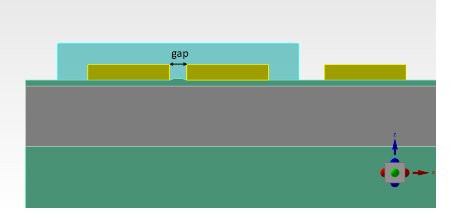
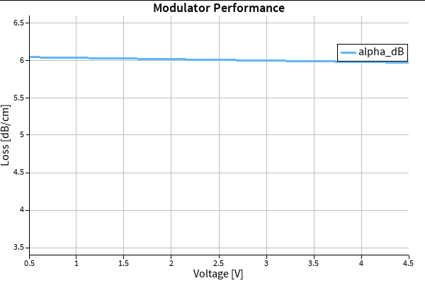
      I wonder if this will work better if you calculate Vpi and loss first and then change the gap before calculating these attributes again. In this way, you no longer need to create the E vs gap matrix (and instead collect Vpi vs gap). As you mentioned, by changing the gap the mesh will change too and therefore, the dimension of the field data will not match. Even if you exclude datapoints to match dimensions, there's not an exact correspondance between E datapoints (e.g. E(1),gap(1) and E(1),gap(2) will correspond to different locations). An alternative may be to calculate average of E for each gap to create avg(E)vs gap but I'm not sure if this will be helpful for your FEEM calculations.

      In any case, specifically for the addattribute error, the issue might be that the added attribute needs to have the same size as the dimensions (x,y,z). There are few examples of this command used in the following two articles which could be helpful: addattribute_command, Lumerical_datasets.

      On another note, I will be away for few weeks during holiday season. Please submit a new ticket in case you need more immediate help in the meantime, so my colleagues can assist you. Best, Khash

Viewing 13 reply threads
  • You must be logged in to reply to this topic.