Hello,
I'm simulating a 100 kHz transformer for a Dual Active Bridge (DAB) converter and I'm running into unrealistic winding losses.
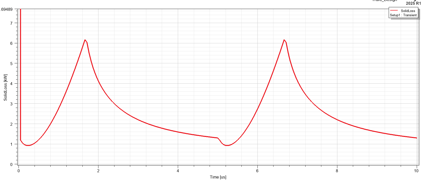
In the first few timesteps, the solid loss spikes to around 50 MW, then settles down to a peak value of about 6 kW. Even this value seems far too high for a 25 kW transformer design.
Here are the settings:
The transformer windings are supplied external by two rectangular voltage sources with rise and fall times of 1e-7 s. Primary Side Resistance 5.27e-3 Ohm and secondary side resistance 11.16 Ohm in the external circuit which should model the end winding.
2D Magnetic Transient Simulation XY
Boundary Condition: VectorPotential: 0
Excitation:
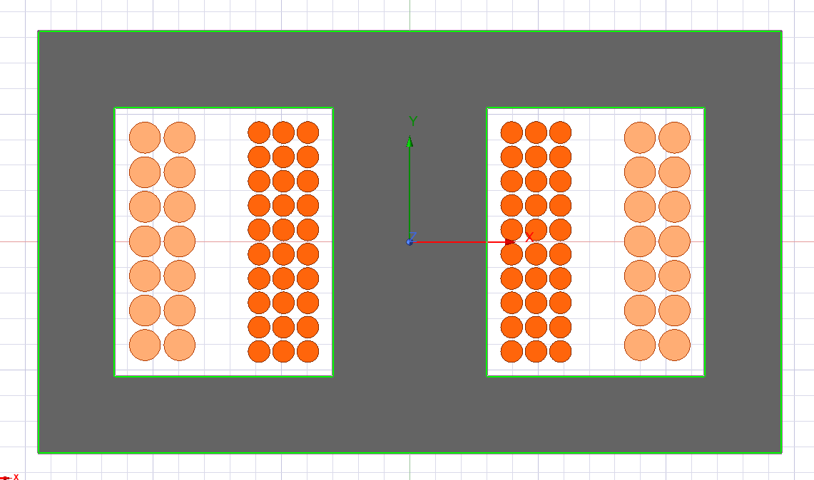
30 coils on primary side were assigned for primary winding and 14 coils on secondary side were assigned for secondary winding.
Number of parallel branches: 1
IsSolid: Solid
Set Eddy Effects: On for every turn
Set Core Loss: On for only core
Mesh: 6400 elements (air 2277, core: 991, turns_pri: 32, turns_sec: 40)
Solver:
Output per object core loss: yes
Output per object solid loss: yes
Time Decomposition Method Option: Periodic and Half-periodic
Materials:
copper_pri: Composition: Litz Wire (Strand number: 223, Wire Dia: 0.1mm)
copper_sec: Composition: Litz Wire (Strand number: 450, Wire Dia: 0.1mm)
Ferrite Core: Core Loss: B - P Curve
Values:
U_in = 800V
U_out = 350V
n1 = 30
n2 = 15
u = n1/n2
r = u*U_out/U_in
phi = pi/3rad
f_sw = 100kHz
stopTime = 0.5*1/f_sw
stepTime = 0.005*1/f_sw
Model depth: 50 mm
Thanks in advance for any input.
Best Regards






















 You are navigating away from the AIS Discovery experience