-
-
August 2, 2023 at 3:31 am
Anoush
SubscriberHi community,
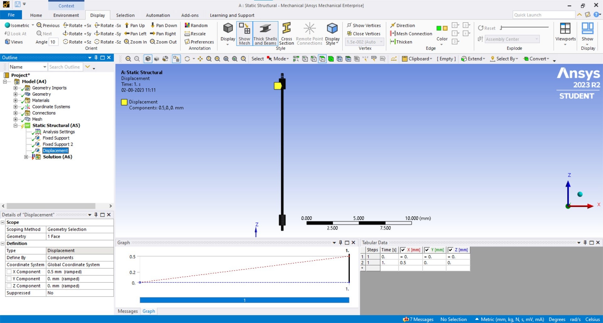
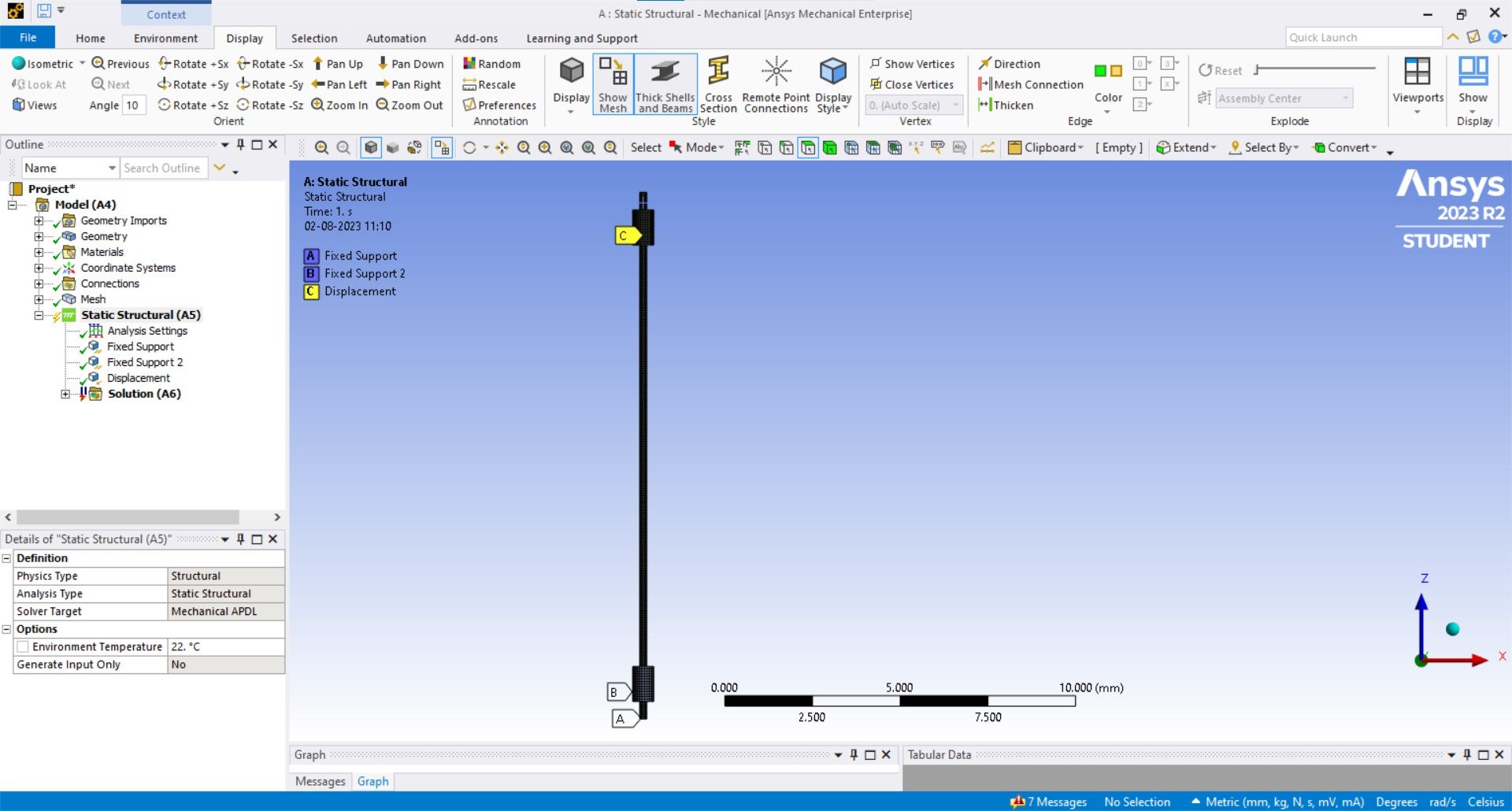
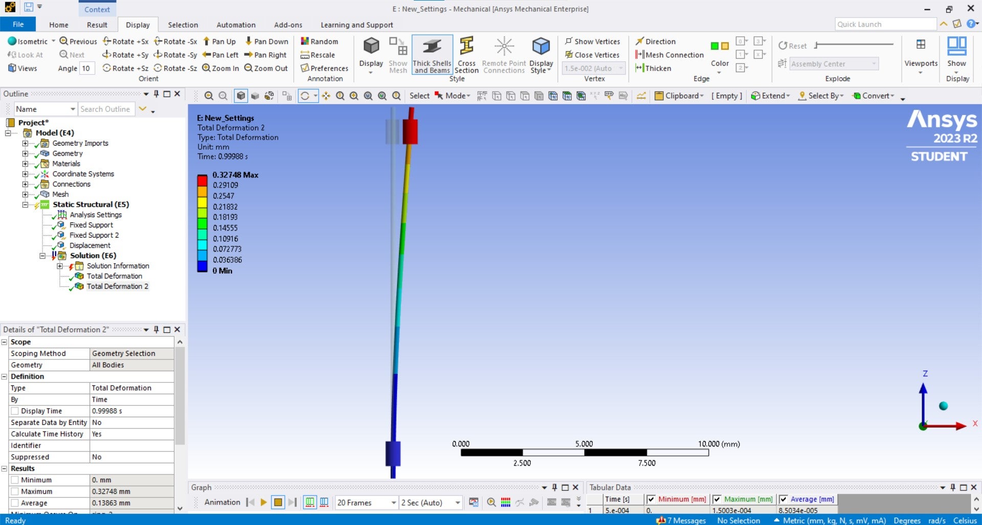
I'm trying to perform a simple copper wire bending to see the resulatant deformation when a aluminium coil around is given a prescribed displacment. I'm using ANSYS student version. But the results aren't the expected one's. The ring slides and moves away from copper wire instead of deforming it due its displacement. I have created contact between those components also added pinball radius. Please suggest me the modifications required. (i.e the images are attached)
Thanks in advance.
-
August 2, 2023 at 5:39 am
Akshay Maniyar
Ansys EmployeeHi Anoush,
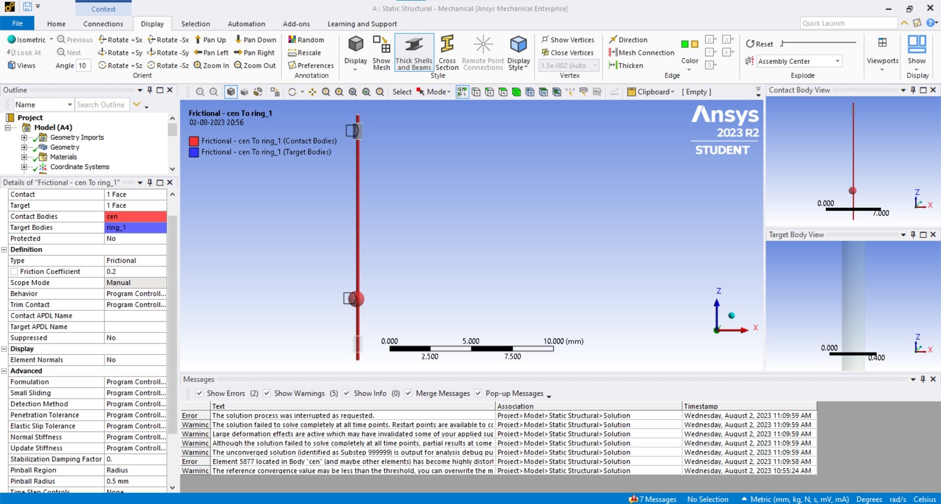
Can you share the contact settings you are using and the deformation plot?
Thanks,
Akshay Maniyar
-
August 2, 2023 at 1:09 pm
Anoush
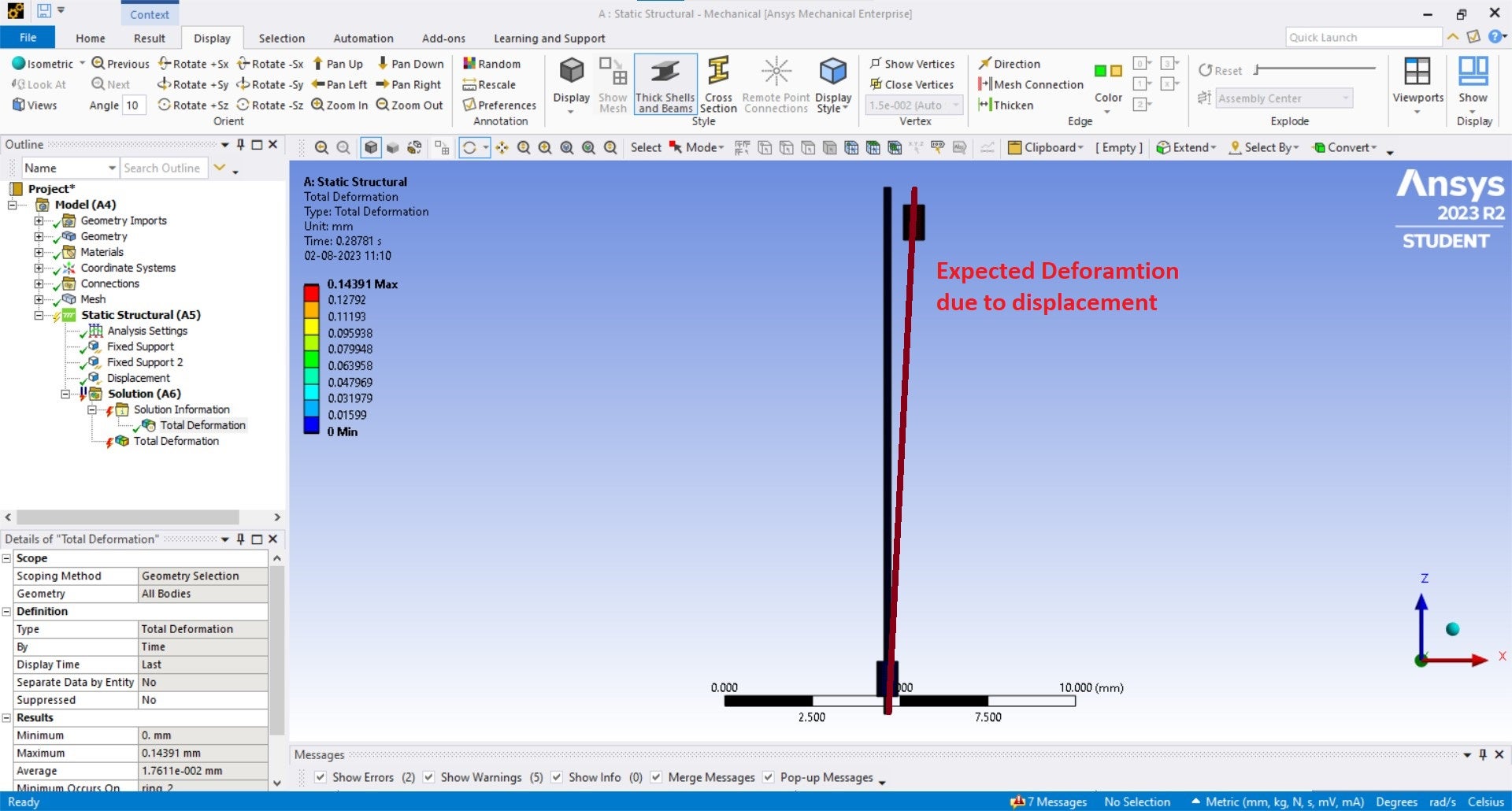
SubscriberThanks Akshay for your assistance. The deformation plot is attached as well as the current contact settings. Also I have included the actual results that were expected for the given boundary conditions and contact settings. I do hope I have provided enough details reuqired to de-bug this issue.
Thanks in advance.
-
August 3, 2023 at 8:45 am
Akshay Maniyar
Ansys EmployeeHi Anoush,
It is mostly because of the gap present between both the parts which are in contact. Can you try to use a small stabilization damping value(maybe 0.05 or 0.1) and then try to run? Also, increase the number of substeps under the analysis setting.
Thanks,
Akshay Maniyar
-
August 4, 2023 at 8:27 am
Anoush
SubscriberHi Akshay,
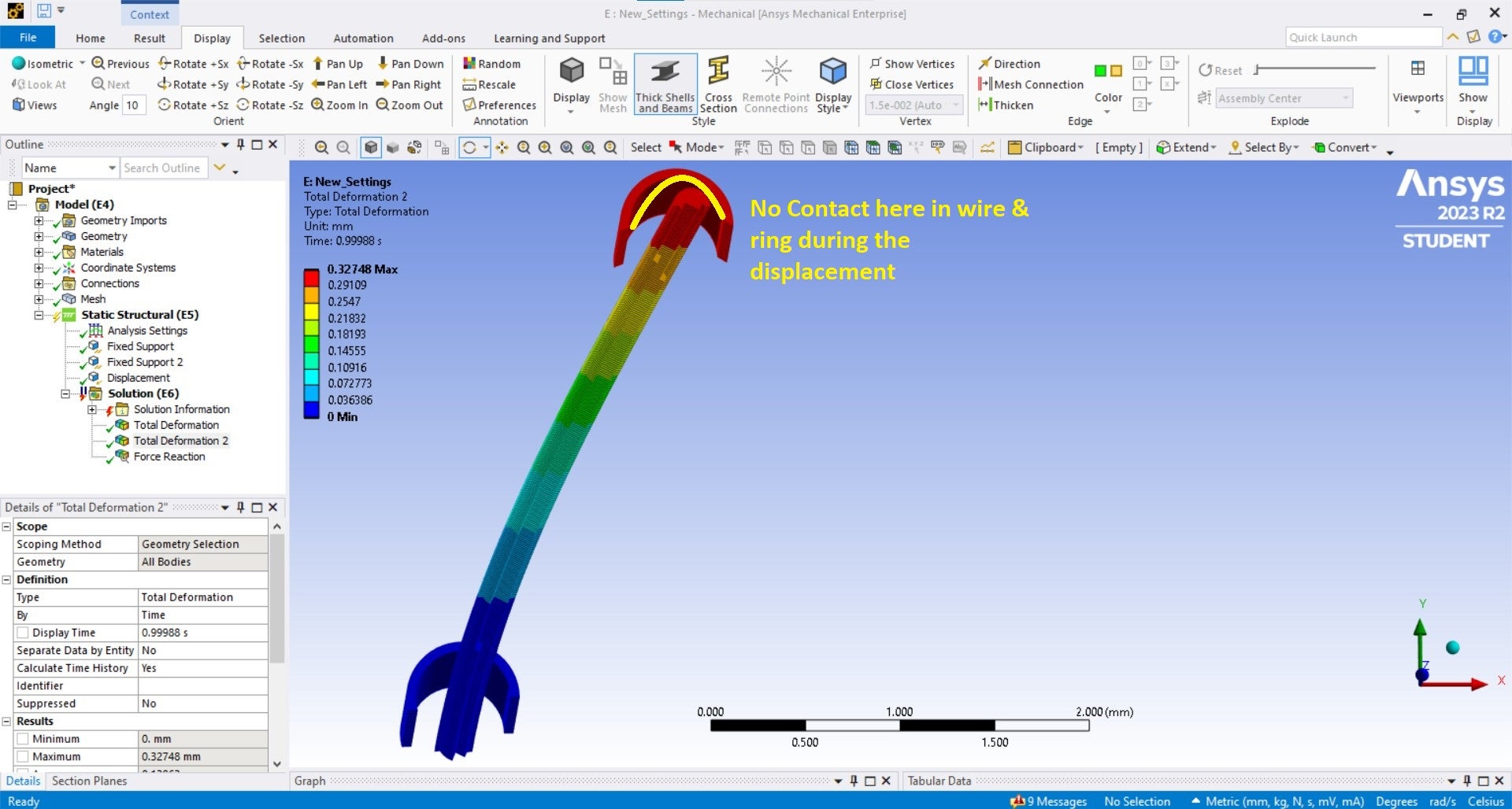
First thanks for you suggestions, I did utilise a smaller stabilization damping value as recommended and I got a fully-converged solution. But I do wish to know what are effects of this factor on contact forces between faces (ring-wire interface).
Question: Also with current pinball-radius (0.5) I could not seeing any ctonact between inner ring face and wire outer face but still the deformation of wire occurs. Please suggest some contact settings on these issue. (attached picture)
Thanks for your assistance.
-
August 4, 2023 at 9:45 am
Akshay Maniyar
Ansys EmployeeHi Anoush,
A contact you define may initially have a near-open status due to small gaps between the element meshes or between the integration points of the contact and target elements. The contact will not get detected during the analysis and can cause a rigid body motion of the bodies defined in the contact. The stabilization damping factor provides a certain resistance to damp the relative motion between the contacting surfaces and prevents rigid body motion.
Contact Stabilization damping introduces artificial energy into the model. This technique can alleviate convergence problems, but it can also affect solution accuracy if the energy imparted by the damping forces becomes too large. It is a good practice to check the stabilization energy and reaction forces as part of the model validation process.
Regarding your question, are you checking the deformation in true scale? It should have contact as deformation is present. You can also insert the contact results under solution information and check the number of contacting points.
Thanks,
Akshay maniyar
-
August 7, 2023 at 1:35 am
Anoush
SubscriberHi Akshay,
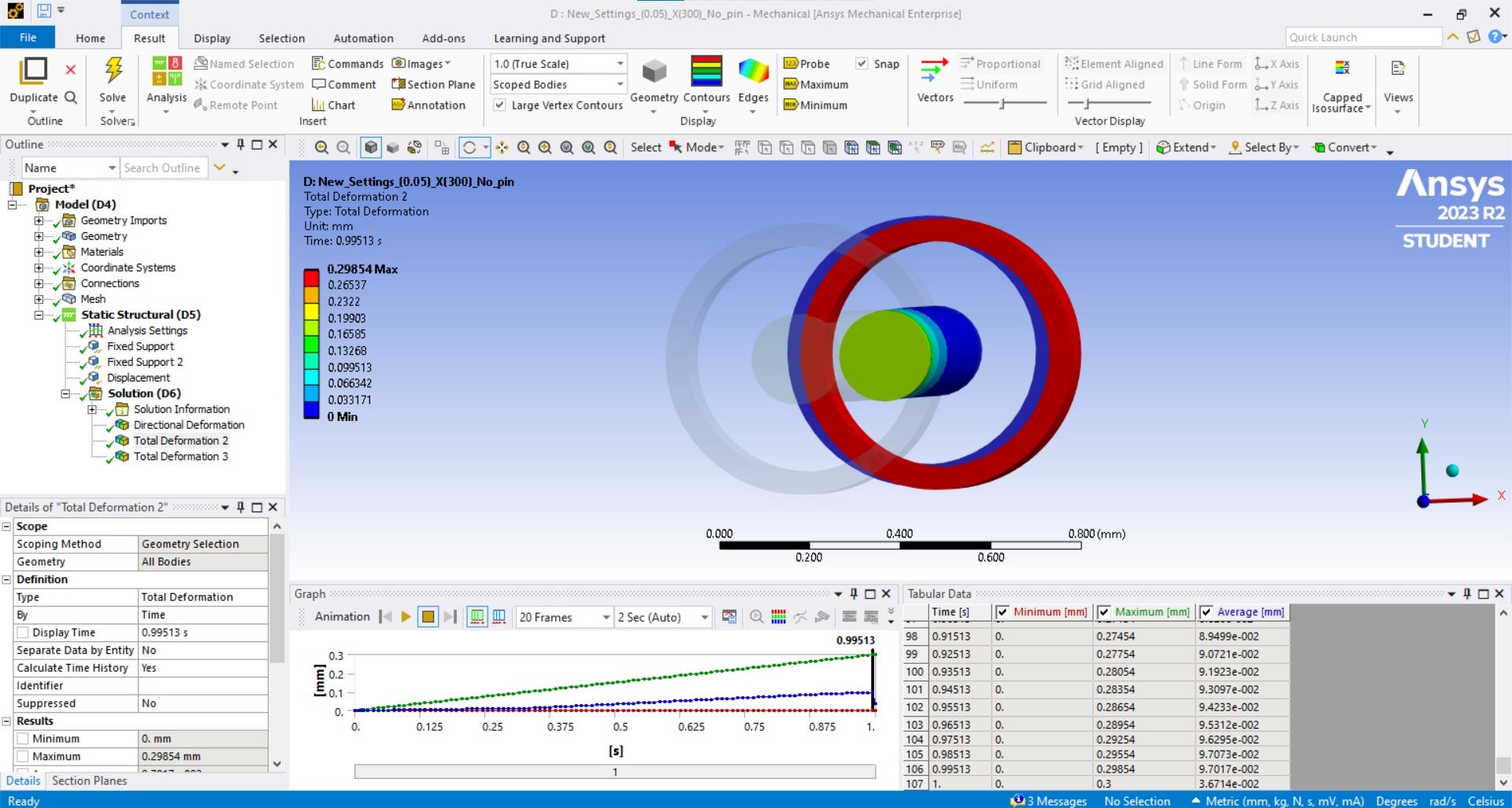
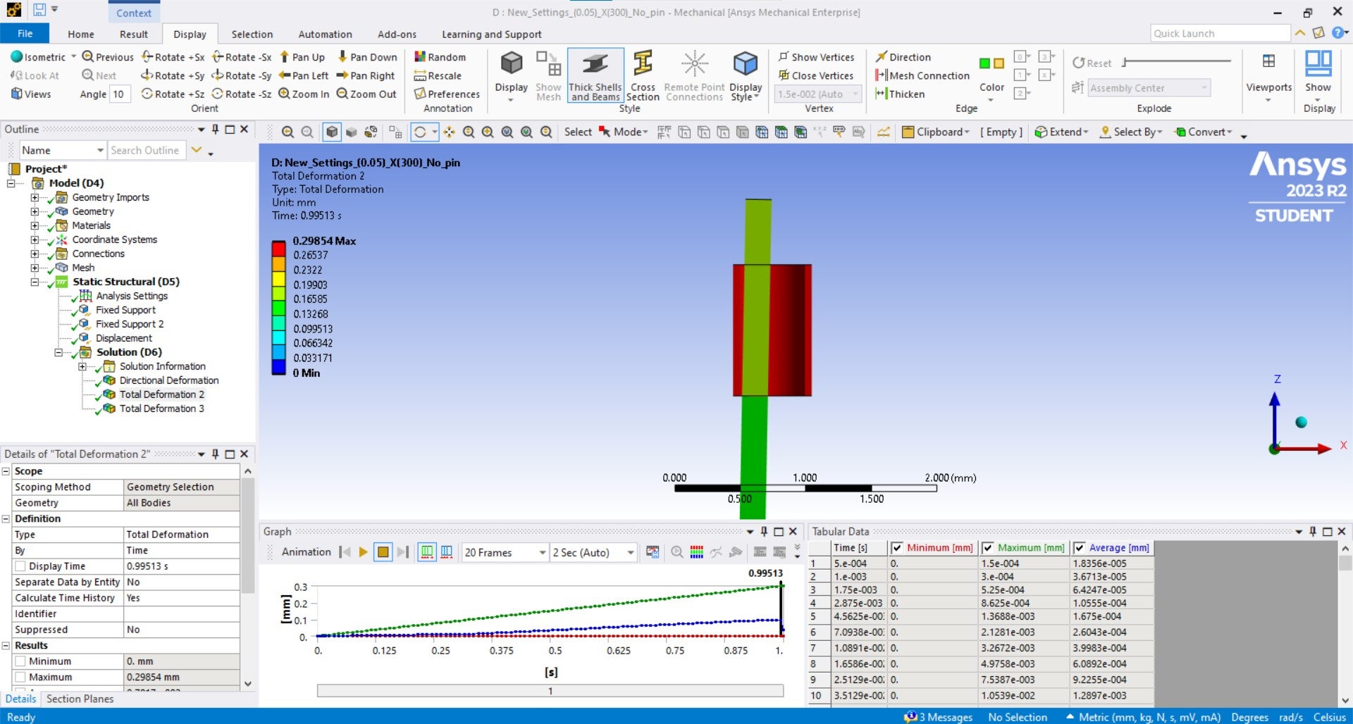
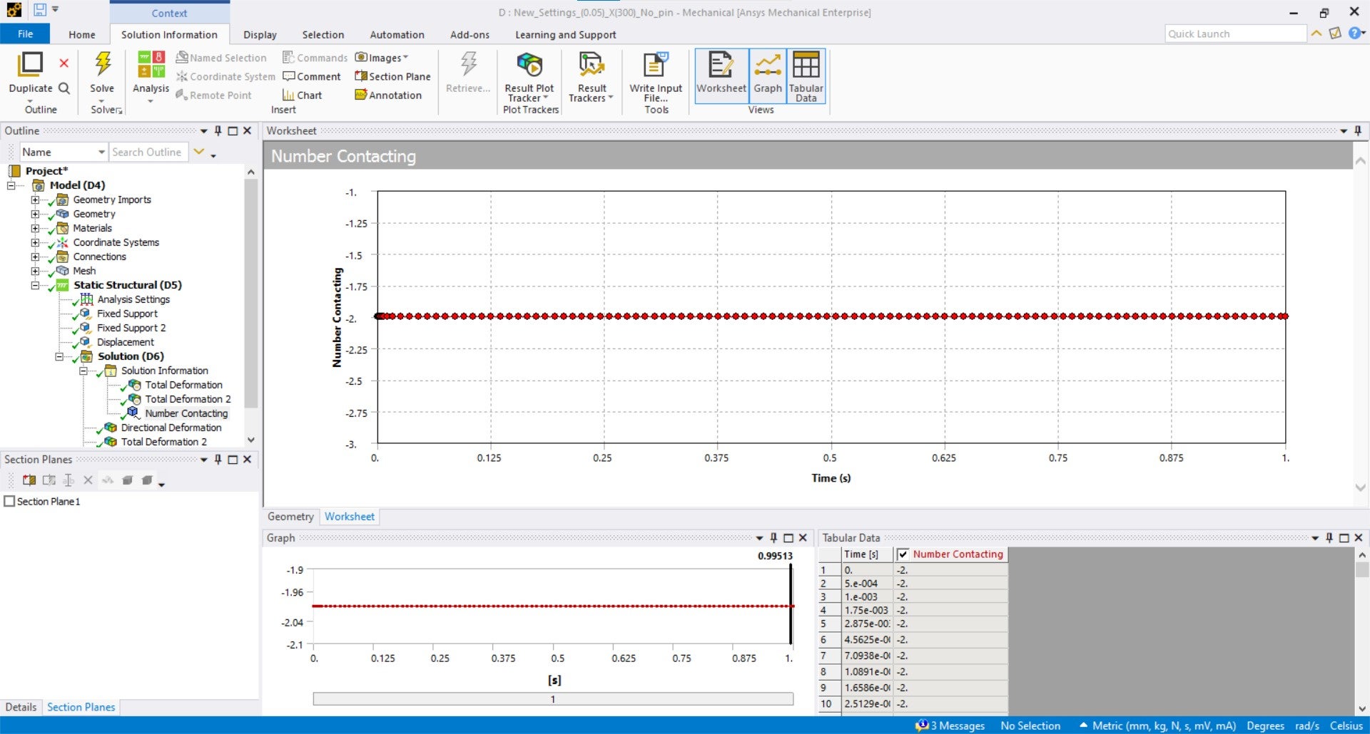
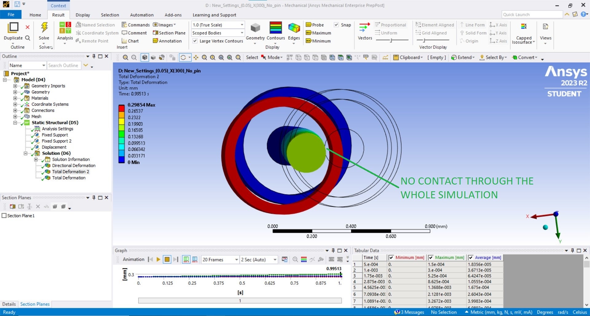
Thanks for your brief explanation on contact -stablization damping, both the recommended values (0.05 & 0.1) did work well forr me in this case. But I do think still some input seetings for contact has issues. I checked the deformation in true scale and also plotted the number of contacting points.
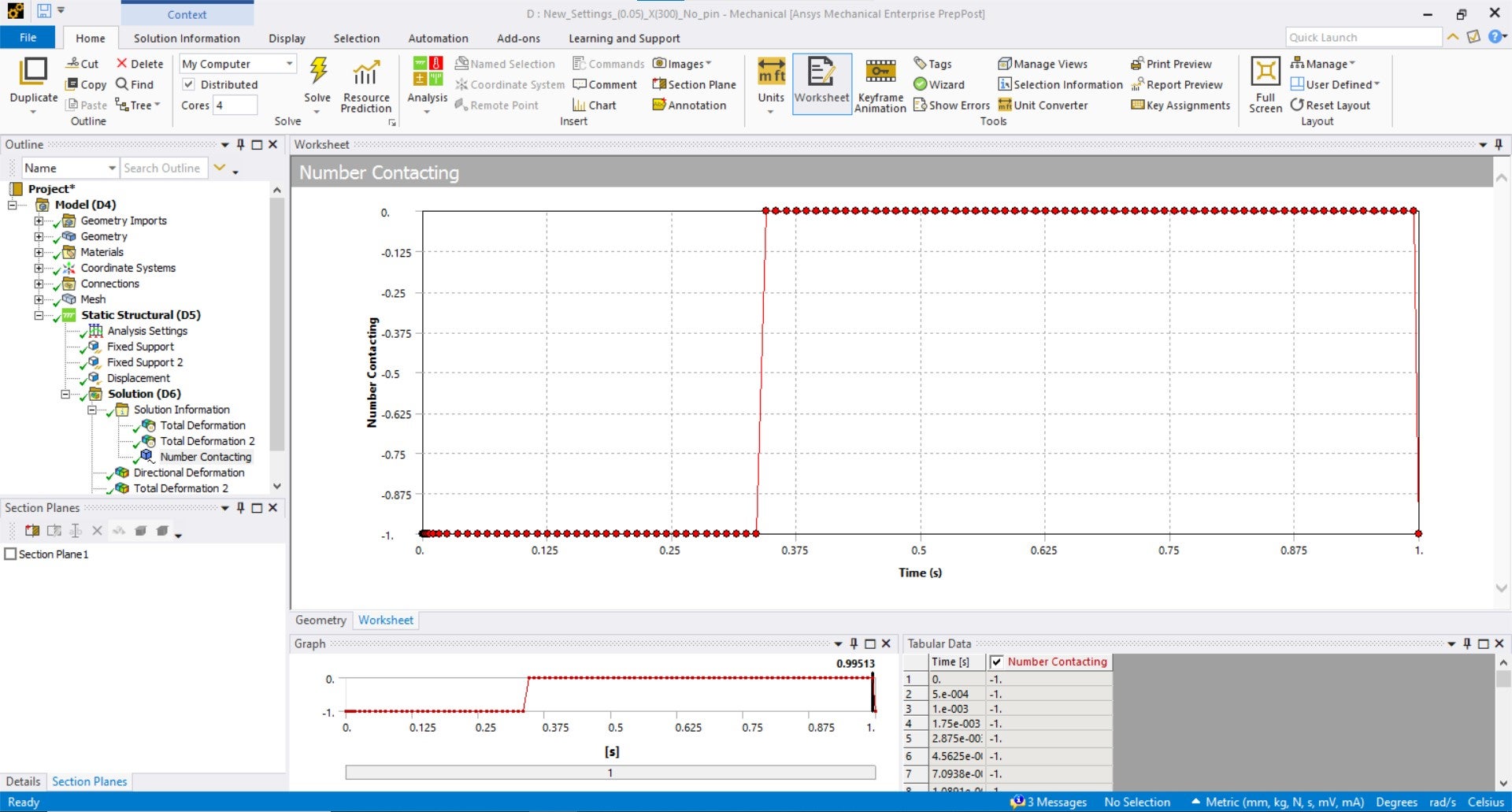
There is no contact between the components in true scale aslo (outer ring and wire). This can be also seen in number of contact points as just 2 locations (pics attached). In this scenario, what are improvements could be further done to improve the results (like contact force and deformation).
Thanks for your time.
-
August 7, 2023 at 7:22 am
Akshay Maniyar
Ansys EmployeeHi Anoush,
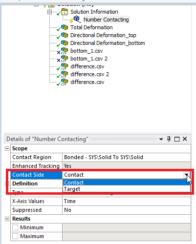
For the number of contacting result can you check the results for the target side too?
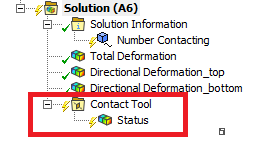
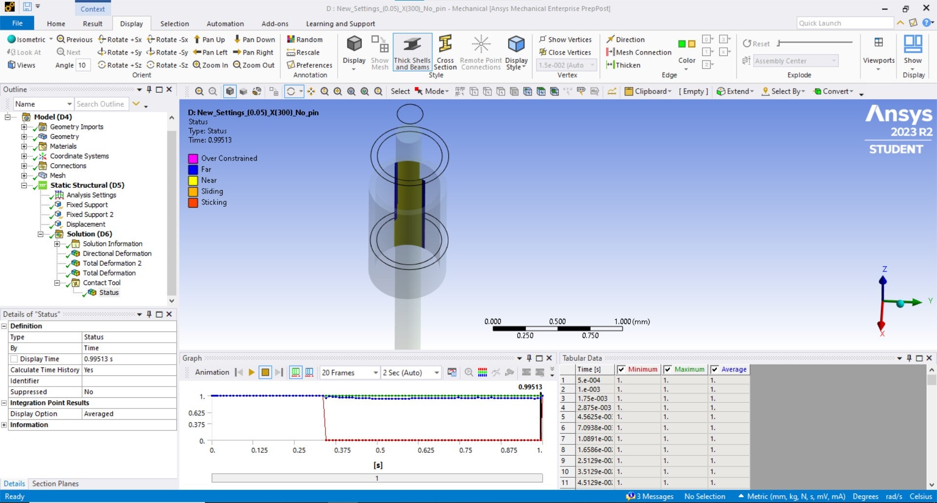
Also, you can check for contact status by inserting the contact tool under the solution. From your attached plots, I guess it is touching the bottom of the cylinder, not at the top of it.
Thanks,
Akshay maniyar
-
August 8, 2023 at 9:42 am
Anoush
SubscriberHi Akshay,
Thanks for your valuable feedback, I cheked once again the contacting results between both ring & wire by both the methods you mentioned and still there seems to be no changes in the results. Also I review all the results in true scale.
As we see in the pictures attached there is no contact between these thus the resultant deformation and forces are very different to that of as expected. Please do help me resilve this issue. Also by any means can I attach my workbench file for your review?
Thanks in advance.
-
- The topic ‘Issue in contact bodies- one contact body has large displacement in resultant.’ is closed to new replies.


-
5159
-
1836
-
1387
-
1249
-
1021

© 2026 Copyright ANSYS, Inc. All rights reserved.

