-
-
September 21, 2018 at 8:41 pm
rorti045
SubscriberHi,Â
I am new working with Maxwell (2 days). I have watched some tutorials and read Maxwell's help, however I am still unable to assign correctly the currents in my model. I have assigned two current on each end of my coil. One is going inside and the other one is leaving the coil. When I request to show the current path the coil doesn't exhibit the expected current behavior. I read that the ends of my coil should be in the same plane. I used that approach but it didn't work. I am working with magnetostaci > Eddy currents mode
I have a piece of metal on top of my coil and a box of air surrounding all my system. I am assuming the problem is within the main piece.Â
I have tried many things but I always get the same result:Â
*Global - Messages
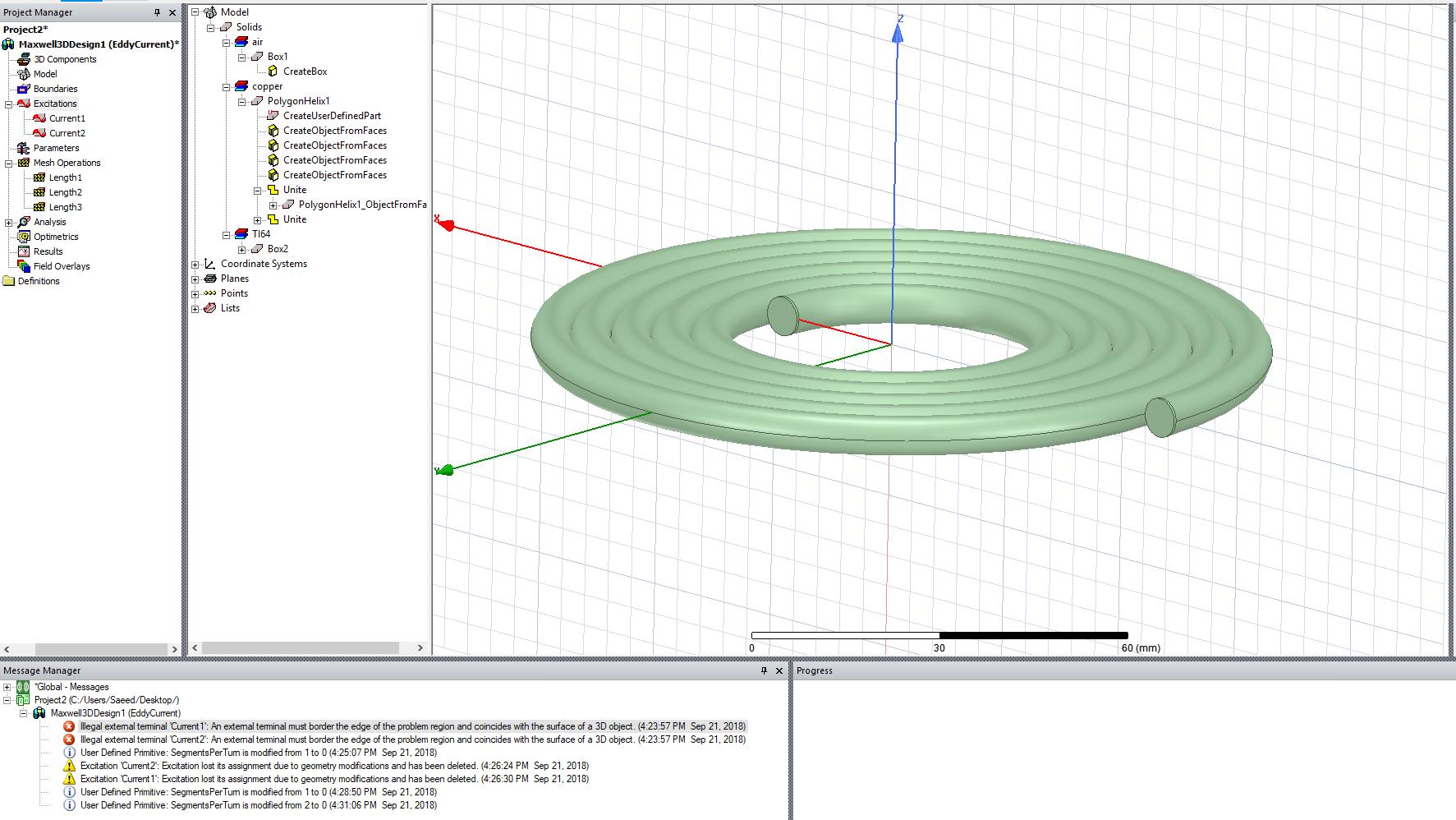
 Maxwell3DDesign1 (EddyCurrent)
  [error] Illegal external terminal 'Current1': An external terminal must border the edge of the problem region and coincides with the surface of a 3D object. (4:23:57 PM Sep 21, 2018)
  [error] Illegal external terminal 'Current2': An external terminal must border the edge of the problem region and coincides with the surface of a 3D object. (4:23:57 PM Sep 21, 2018)
-
September 21, 2018 at 8:54 pm
-
September 24, 2018 at 2:32 am
Mark Christini
Ansys EmployeeIn Maxwell 3D, you must always provide a complete path for current to flow, either in a closed conducting loop or by entering and exiting the region wall. Current cannot flow into the air region (your coil above) with nowhere to go, just like current cannot flow on the test bench in a spiral coil which is not connected to anything. Â
In addition, there must be a physical gap or insulation boundary between turns to prevent them from shorting out.
Please reference Maxwell online help topic:Â "Introduction to Maxwell"Â for a description of the various solvers and their capabilities.
-
September 24, 2018 at 4:47 pm
rorti045
SubscriberMany thanks for your suggestions.Â
Unfortunately, your tips and suggestions didn't solve my problem. Apparently, the box containing the problem MUST be in touch with the coils end, otherwise the problem will present.
Again, many thanks for your help. -
January 12, 2019 at 7:36 am
Deeb
SubscriberDid you solve the problem or not yet ?!Â
Â
-
April 24, 2019 at 7:53 am
ikra
SubscriberI have the same problem, could you help me please I don't know how I must do ! Â
-
April 25, 2019 at 3:16 pm
Yijiang Jia
Ansys EmployeeLike @mchristi said, Maxwell only accept the current excitation formed as either closed loop or start & stop. Putting the two start & stop sheet objects in the middle of the solving space would never successfully assign a current excitation. In your case, you may want to try only model a half of the coil and the start & stop sheets can then be placed on the solving region box.Â
If your simulation goal is merely extract the paracitics (LCRs) of the coil, ANSYS Q3D may be the tool for you. In Q3D, the excitation shown in your screen shot is allowed.
-
August 27, 2020 at 2:56 am
Fummy
SubscriberYou need to put the CoilTerminal_1 and CoilTerminal_2 on the same surface of Region.nOf course, you also need to modify the lead wires and Region parameters.nn
-
November 30, 2020 at 10:20 pm
XuBinHan
SubscriberYou have to make sure your start terminal is aligned at your designed boundary of the vacuum or air or this mistake happensn
-
- The topic ‘Unable to assign correctly the excitations in a coil’ is closed to new replies.
-
3762
-
1333
-
1168
-
1090
-
1014
© 2025 Copyright ANSYS, Inc. All rights reserved.