-
-
June 22, 2021 at 6:45 pm
OROI
SubscriberHi
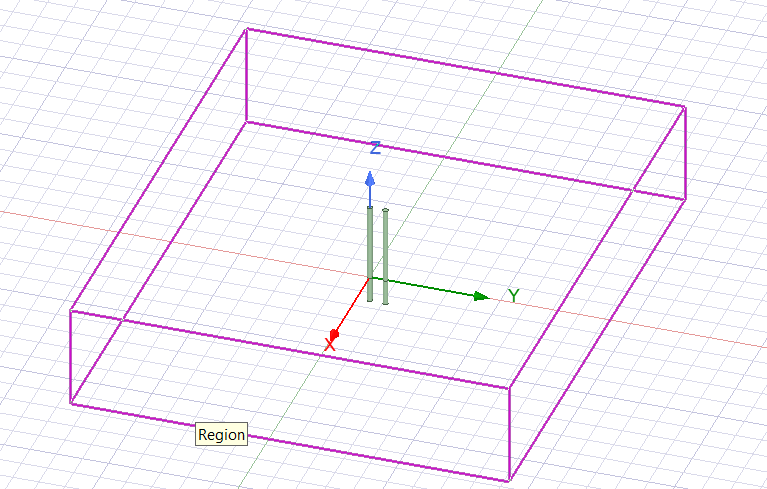
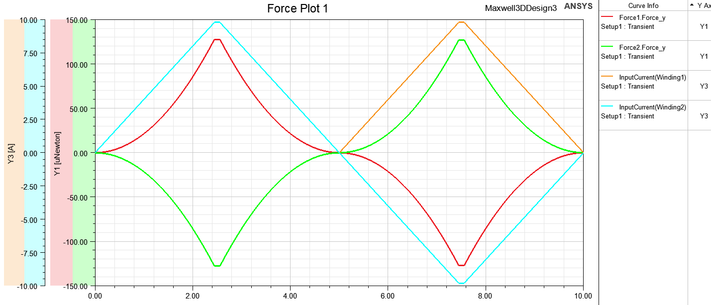
Why forces between conductors do not change direction like it should? Plot shows that in first 10ms, current is flowing same direction in both conductors and after 10ms current flow is opposite. When current is flowing same direction conductors should have an attractive force and plot shows that is correct. When current is opposite, conductors should have repulsive force, but plot shows that it is not, which is not correct. Why simulation act like that?
June 25, 2021 at 5:57 pmHDLI
Ansys EmployeeHello OROI There are some information related to this issue.
1). Meshing: We may have a good meshing on the geometry and surface, because absolute values of two forces should be same. It means total force would be zero. We could do meshing linking between magnetostatics and transient solver.
2). Region: we need a big region to cover the geometry for accurate results. I suggest to make 5000 for X direction of this model.
We should get the following similar results. Thanks.

 HDLI
HDLI
June 28, 2021 at 3:04 pmOROI
SubscriberHi
I made larger region and now when the current is opposite, conductors have repulsive force like it should, but force value is smaller. Is there any information of that "meshing linking between magnetostatics and transient solver" how to do it?
July 12, 2021 at 4:22 pmHDLI
Ansys Employee
For "import mesh", please review the manual on "Import mesh" in Maxwell Help>Specifying Solution Settings>Setting Analysis Parameters for Transient Solutions>Setup Link for Transient Solutions. Thanks.
HDLI
October 18, 2021 at 7:09 pmOROI
SubscriberHi
I tried setup link for transient solution, but i got error "The source and target models should be geometrically equivalent". I don't understand why source and target geometry is not equivalent?
Here is screenshot https://ibb.co/FJG6nWW
Viewing 4 reply threads- The topic ‘Two parallel conductors’ is closed to new replies.
Innovation SpaceTrending discussionsTop Contributors-
4728
-
1565
-
1386
-
1242
-
1021
Top Rated Tags© 2026 Copyright ANSYS, Inc. All rights reserved.
Ansys does not support the usage of unauthorized Ansys software. Please visit www.ansys.com to obtain an official distribution.
-
The Ansys Learning Forum is a public forum. You are prohibited from providing (i) information that is confidential to You, your employer, or any third party, (ii) Personal Data or individually identifiable health information, (iii) any information that is U.S. Government Classified, Controlled Unclassified Information, International Traffic in Arms Regulators (ITAR) or Export Administration Regulators (EAR) controlled or otherwise have been determined by the United States Government or by a foreign government to require protection against unauthorized disclosure for reasons of national security, or (iv) topics or information restricted by the People's Republic of China data protection and privacy laws.


