-
-
November 21, 2024 at 7:36 am
hassan.currimbhoy
SubscriberHello all,
I am currently simulating an FEA model of an IPMSM in Maxwell at an operating point of 1000 rpm and 100 Nm. The drive currents at this operating point have an rms amplitude of 136.8 A and have a phase advance of 27.92° electrical. According to motorCAD, the D and Q axis flux linkages should be 63.3 mVs and 65.87 mVs respectively.When I simulate the machine in Maxwell alone, I obtain these values and the torque is 100 Nm as expected.
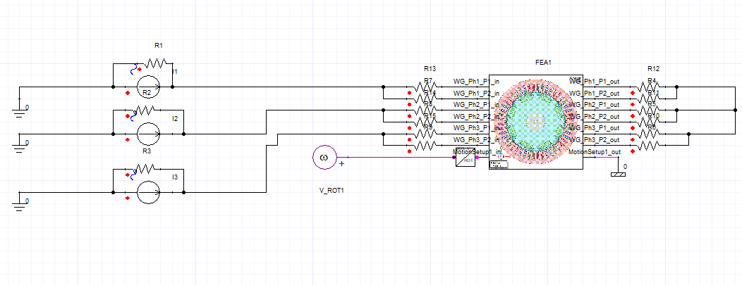
I want to now link the maxwell model to simplorer and drive the machine with an external circuit. The simplorer model is looking like this:

The machine windings have been purposely connected in the depicted manner such that a parallel-star connected machine results.
I have added a parallel resistance to each ideal current source and resistances before/after each input and output port of the machine model in accordance with the Twin builder connection requirements.Transient-transient link has been enabled in Maxwell and the end time set in Maxwell solution setup is greater than the one set in TB aswell.
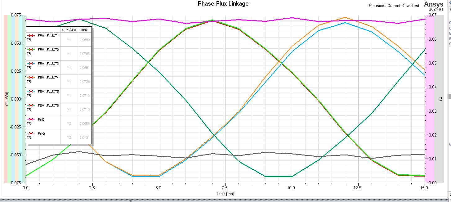
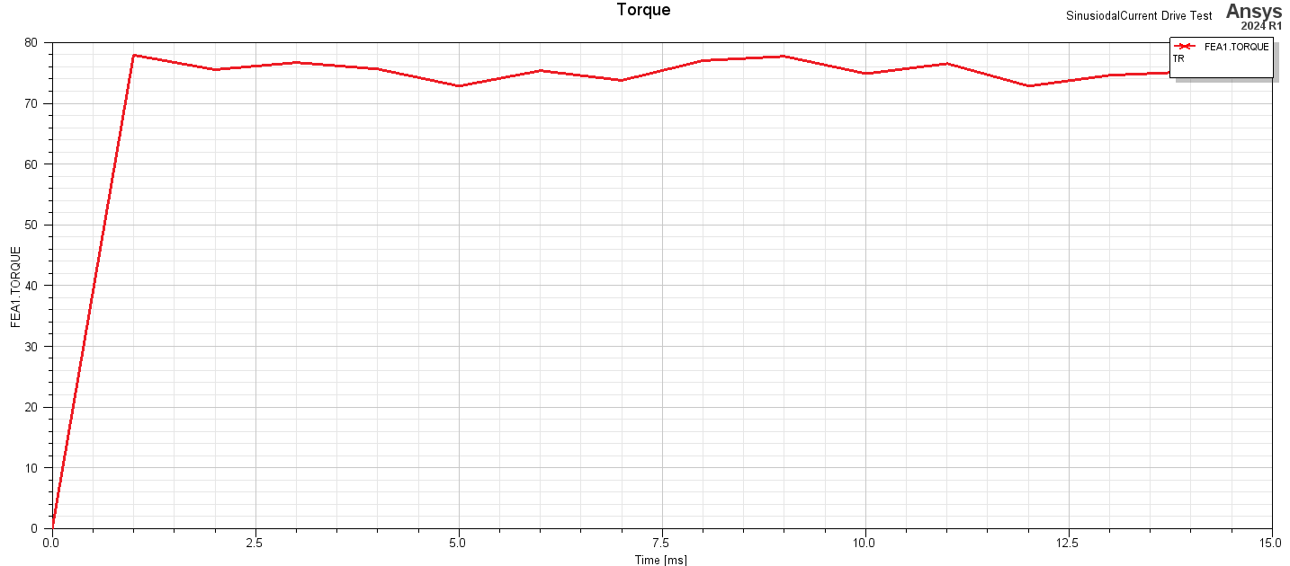
When I simulate in TB, the results do not match the expected values as shown below:

D flux linkage is close to its expected value of 63.3 mVs, while the q flux linkage at 10 mVs is way off from 65.87 mVs.

The torque is approx. 23 Nm less than the target, which I believe is linked to the low q flux linkage.
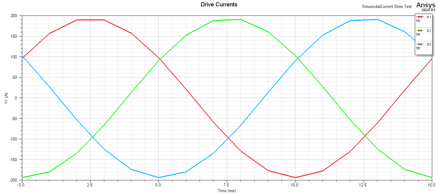
These are the drive currents that I am feeding to the machine.
Does anyone have an idea why this is the case when I simulate in TB? Any help would be greatly appreciated!
If you need more information about the model and its settings just let me know.
Thanks in advance,
Hassan
-
- You must be logged in to reply to this topic.


-
1091
-
447
-
396
-
225
-
201

© 2024 Copyright ANSYS, Inc. All rights reserved.


