TAGGED: 2-way-coupled-fsi
-
-
October 17, 2024 at 3:09 pm
ashishkumar.gupta
SubscriberHello,
Is there any video or documentation telling how to perform 2 way simulation of systems like Ball bearing with lubricant.
In this, the ball rotation causes the oil to flow and not vice versa where fluid flow causes impact on Solid...
I am doing Transient Mech - Fluent - SC.
Any help?
Thank you
-
October 17, 2024 at 3:25 pm
Rob
Forum ModeratorDo you need the Mechanical part? If there's no material deformation it's at worst a 6DOF problem.
-
October 18, 2024 at 6:06 am
ashishkumar.gupta
SubscriberHello Rob, Thank you for ur response
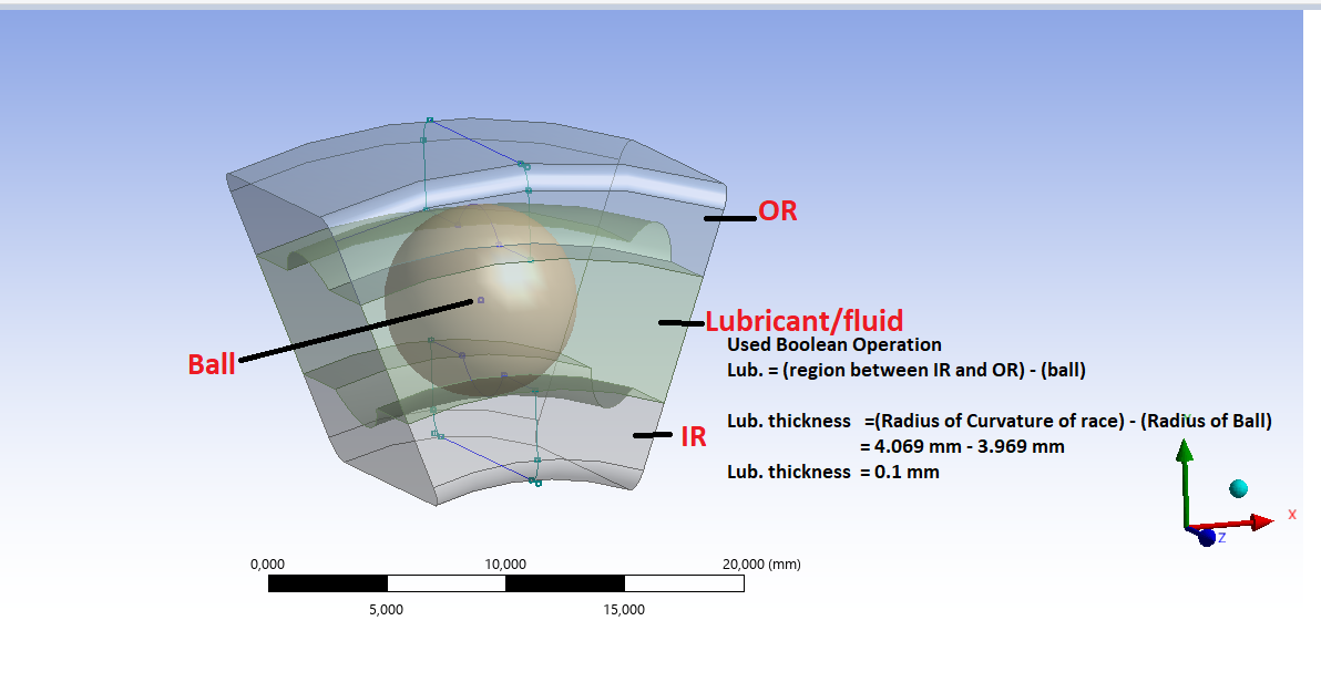
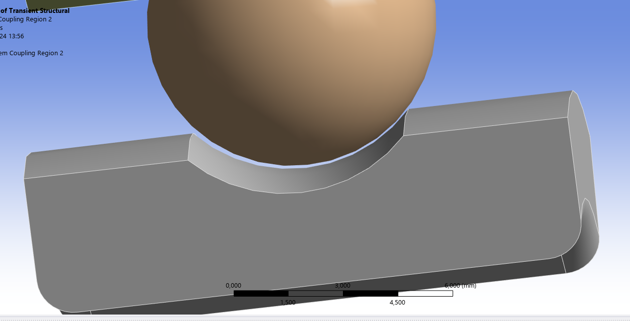
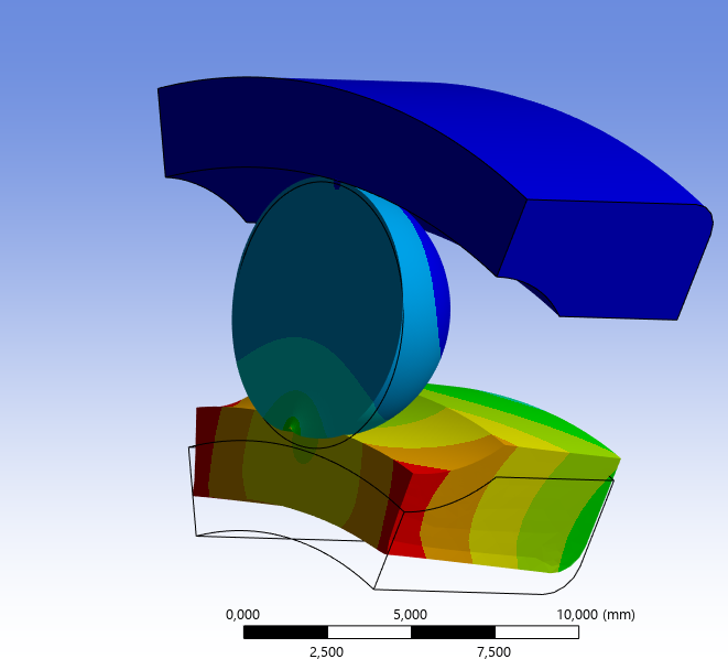
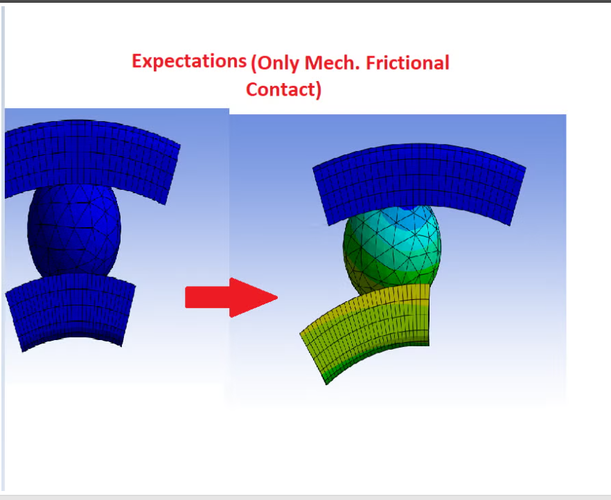
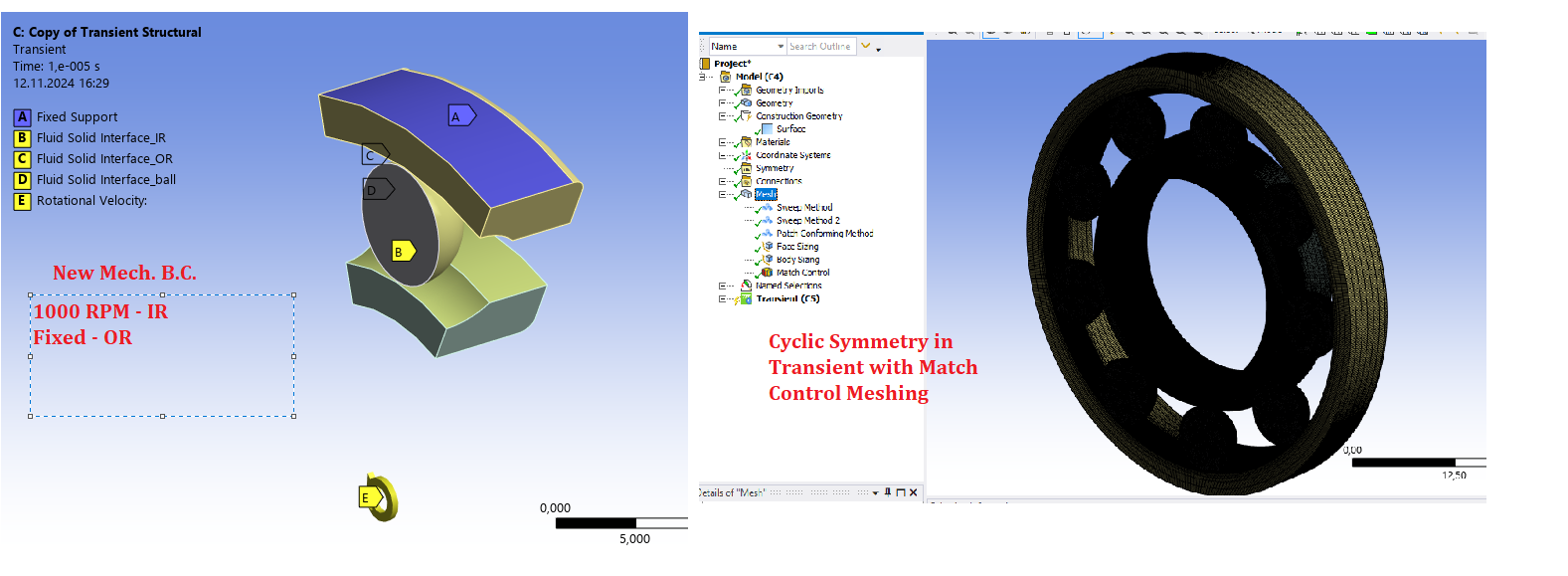
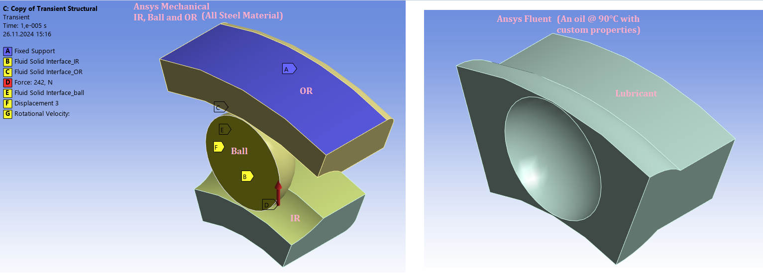
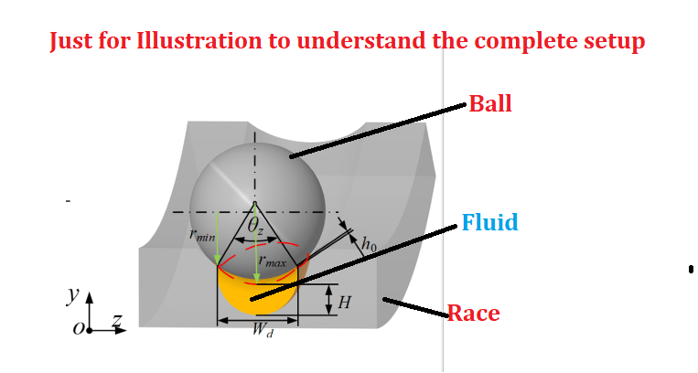
I have prepared a model with a ball, IR and OR too see the effect of Lubricant on the Hertz Contact region so as to minimise the friction and wear. From the figure, Oil will always be present between the ball & Race --> Elasto-Hydrodynamic Lubrication
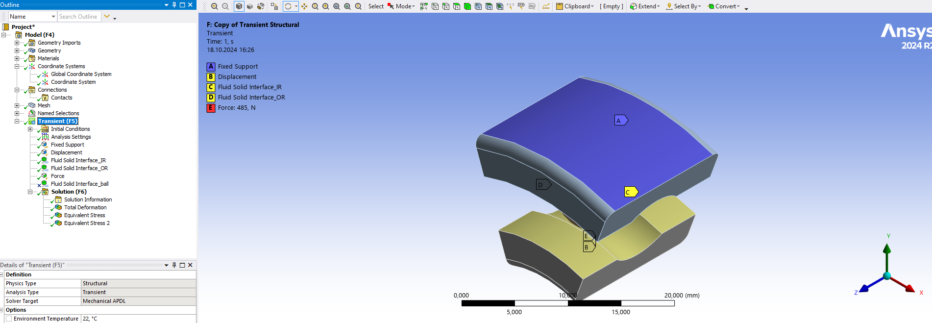
IR rotates (by giving circumferential Disp.) and radial force also applied bcoz of shaft and OR is fixed ---> in Mech. Structural Transient
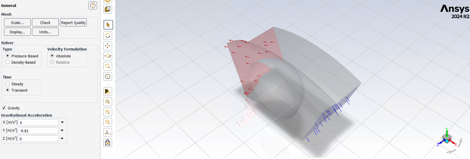
Lubricant inlet on left side and outlet on another. Isothermal, incompressible fluid and SST k-w model used with Dynamic Meshing -- > in Fluent
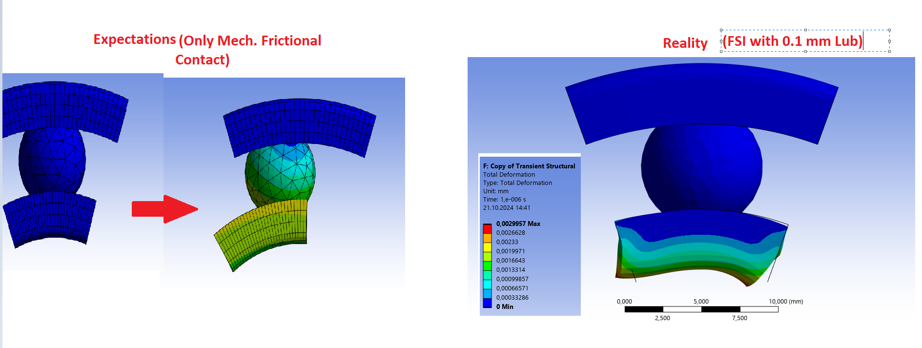
But the model does not run as there is no direct mechanical contact (in Transient) between ball and races. What am I doing wrong here?
P.S. Mapping is 100% between ball and IR & ball and OR. I have developed all this from the Reed valve tutorial and other documentaion.
-
October 18, 2024 at 10:41 am
Rob
Forum ModeratorIf the ball touches the race you can't use the CFD solver: you can't move contact points. When there is a gap it needs to be resolved and I don't see what deforms to need the Mech solver.
-
October 18, 2024 at 11:37 am
ashishkumar.gupta
SubscriberSorry I do not understand your POV. As I am new into this System Coupling thing, I am unaware of the Solver/BC settings to be taken care of.
-
October 18, 2024 at 12:29 pm
Rob
Forum ModeratorIn CFD the mesh is the geometry, so you can't change the surface geometry: that means no moving contact with the 6DOF solver. That will also effect any FSI models. If there is a fluid gap, then it needs resolving. You may need to look at a range of content and tutorials as no one source is going to cover everything.
-
October 18, 2024 at 12:33 pm
ashishkumar.gupta
SubscriberYes exactly I do understand. But I do not know exactly where I am going wrong. Can u suggest some relevant documentation or videos?
This is the gap filled by the Lubricant. Also, I do not understand "In CFD the mesh is the geometry, so you can't change the surface geometry: that means no moving contact with the 6DOF solver."...
Sorry for thr trouble but I am entirely new into this and my Thesis deadline is coming up ...
-
October 29, 2024 at 1:53 pm
Rob
Forum ModeratorFSI is used when we're deforming the solids. If the solid shape is unchanged we don't need to include those effects and "just" need so consider the motion of the parts: 6DOF will handle that. You'll need some constraints to prevent solid contact.
FSI and new to the software is a really bad combination. There's a reason we always try and start simple and work up to complicated. A full FSI model, possibly with 6DOF isn't an application for a new user: I'd be getting help from colleagues for this as it's outside of my normal area.
-
October 29, 2024 at 3:18 pm
-
-
October 29, 2024 at 3:57 pm
Rob
Forum ModeratorIf they're deforming how are you preventing contact? With the first image you can't use CFD as you have contact. With no contact what causes the deformation?
I've seen multiple threads on this topic, and other than point you to the examples and documentation there's not much we (Ansys staff) can add to those. Hence my suggesting carefully thinking about the physics.
-
October 30, 2024 at 7:23 am
-
-
October 30, 2024 at 11:52 am
Rob
Forum ModeratorDoes it deform enough to alter the flow? If the deformation is not altering the flow decouple the two. If the flow is effected you need FSI and 6DOF with the more complex UDF to prevent contact.
-
October 30, 2024 at 11:57 am
ashishkumar.gupta
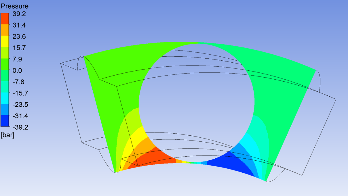
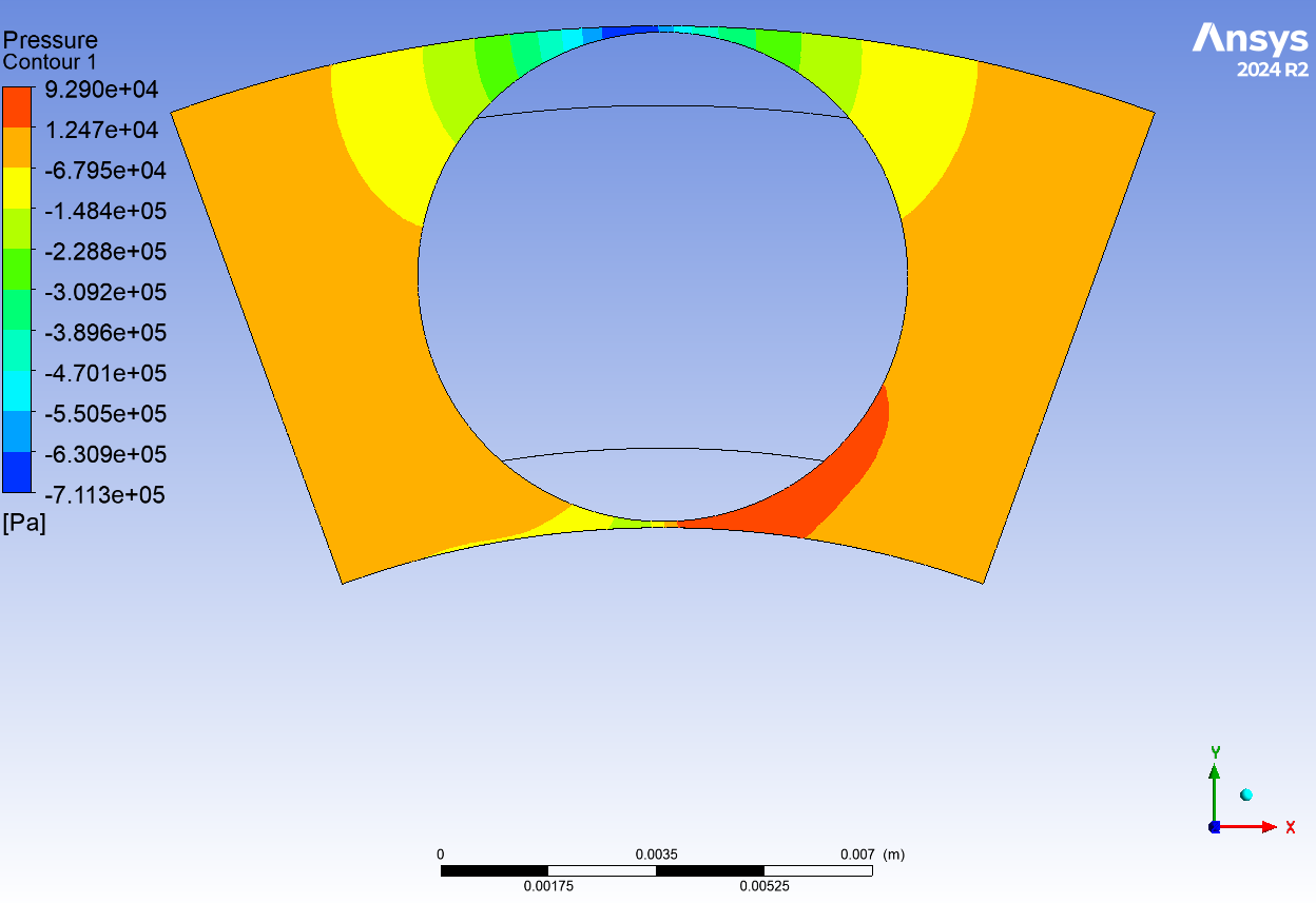
SubscriberThe pressure in the contact should increase (in GPa) usually as it is a very narrow region.
My focus is the stresses on the Race way. It should ideally reduce or there should be some chnages on the race if the lubricant film is always present between the 'Ball and Race. That is the reason of using FSI. But as the Ansys Expert, do u think my idea is physically implementable since I am using periodic function and not the complete Ball bearing. Please help me out to complete the project on time. Thank you!
-
-
October 30, 2024 at 1:58 pm
Paul Hutcheson
Ansys EmployeeHi Ashish,
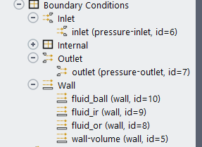
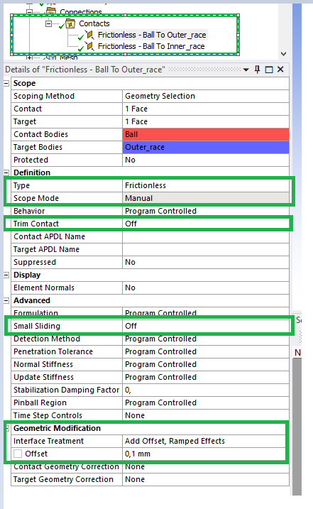
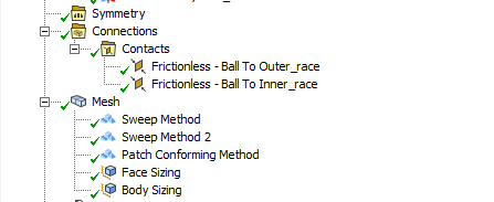
Rob told me to contact you on this thread as an FSI expert.I would say keep the Mechanical model even if bearing has negligible deformation, since in Mechanical you can model mechanical contact between deformable bodies. For FSI you need a contact region defined (frictionless type with offset defined with value equal to the gap you want to maintain so that the CFD mesh doesn't squash). I don't see a contact region defined in the above pictures.
As for the periodic interface, this is fine if the flow is periodic and it gives you accurate bearing loads. No problem from FSI perspective.
Paul-
October 30, 2024 at 2:17 pm
ashishkumar.gupta
SubscriberThank you Paul for jumping into the topic and helping me out.
1. So I can continue withe FSI setup and same Mech. and Fleunt BC and solver setup..right? I just have to DEFINE MANUALLY frictionless contact between IR & Ball and OR and Ball with contact offset equal to Lubricant thickness (0.1 mm in my case).
Also, now I have 3 FSI (IR, Ball and OR) with Turbulent model (SST k-w). My timesteps is 1E-07 s and I want to do simsualtion for 1000 time steps. In Fleunt, coupling iteration is 20 now.
With 10 timsteps my model was running.
2. With 1000 time steps, it is giving 'Negative Dynamic Mesh volume' --- > how to resolve that. (Meshes are quite fine now especially at contact with 0.05 mm and 15 inflation layer).
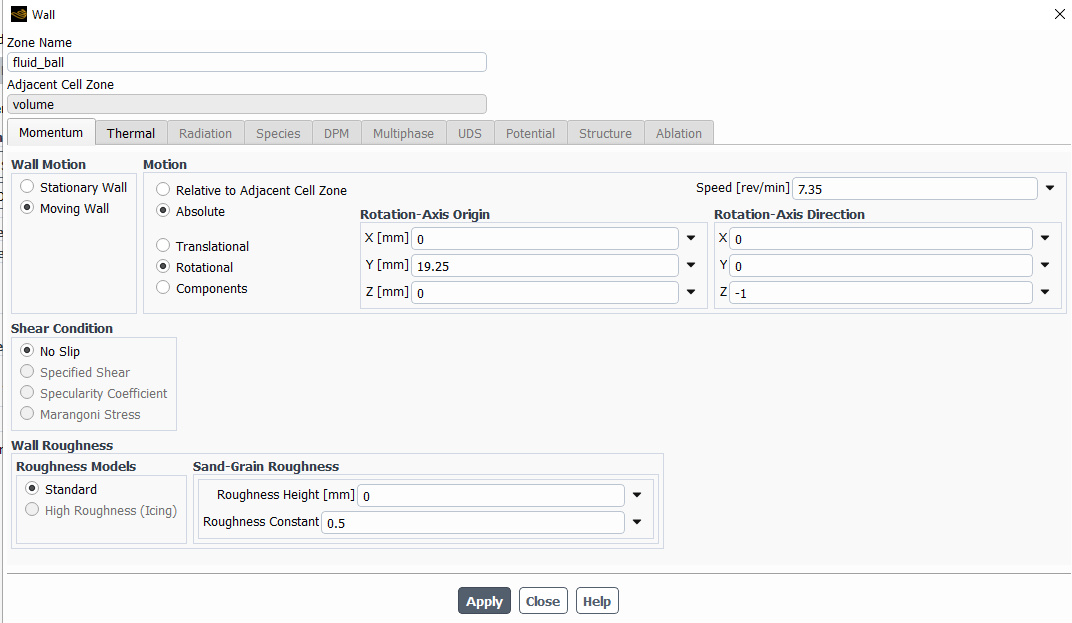
3. what should be the BC in Fluent for IR, Ball & OR? I have analytically calcualted some speed and gave that (Moving Wall with Roational speed arounf their axis)...Is that correct? Because in Mechanical I was just giving Disp. to IR and fixed support to OR and because of contact Ball was rotating.
-
-
October 30, 2024 at 2:40 pm
Paul Hutcheson
Ansys EmployeeHi Ashish,
- Going from Fluent standalone to Fluent within FSI with SyC, you need to reduce iterations per timestep since it is now iterations per coupling iteration. I recommend 3-5 instead of 20. Going from Mechanical standalone to Mechanical within FSI with SyC, you need to set 1 substep and 1 loadstep. Turn off auto timestepping. This is all covered in training.
- Fixing negative volumes depends entirely on what the mesh was trying to do at the time and under what local constraints. I have no idea what it’s doing without seeing an animation or a visual of where the negative volumes are, along with a view of the surrounding mesh to understand the mesh motion in that location. Most often, negative volumes arise due to adjacent walls not having appropriate dynamic mesh zones assigned to them (e.g. symmetry planes with no deforming plane definition allowing nodes to move in plane). It is important to consider how moving walls will affect adjacent walls which are fixed. Or, negative volumes arise due to the motion being too large in one timestep. 1e-7 s seems small to me, but I don’t know the velocity the nodes that went negative were moving at the time or the size of the local cells that went negative. A good rule of thumb is a motion of one cell length per timestep.
- If IR, Ball and OR walls are FSI boundaries, i.e. exchanging force and displacement with Mechanical via SyC they have to have System Coupling dynamic mesh zone type set in dynamic mesh panel. The wall velocities in Fluent will affect only the wall shear stress, which will be included in the total force sent to Mechanical. The wall velocities will not affect the motion on the Mechanical side. Displacement is sent from Mechanical to Fluent remember, not the other way around, so make sure set the motion on the solver side that is driving the motion and the other solver will follow.
To set expectations, I have many commercial customer engagements and unfortunately won’t be able to keep a continuous dialog here. This is a complex analysis, in my opinion too late to tackle with a thesis deadline approaching, but I wish you luck.
Paul
-
October 30, 2024 at 2:58 pm
ashishkumar.gupta
Subscriber3. So could you please suggest me the BC for the Fluent wall? Like if I choose 'Moving wall', I have to give some velocity...right?
In Mech, IR and Ball roates but OR is fixed. what to give in Fluent?
I just want to see some motion in FSI as I see in Mech. I can then maybe done with my task.
I understand you are overloaded but a small request from my side to help me atleast run the model as accuracy is not my Goal here. Because if someone else takes it, he will start from 0 again.
-
October 30, 2024 at 4:31 pm
Paul Hutcheson
Ansys Employee3. If Mechanical FSI walls are rotating and you are sending displacement to Fluent FSI walls, there is nothing needed to set in Fluent on the wall. Keep it as no slip.
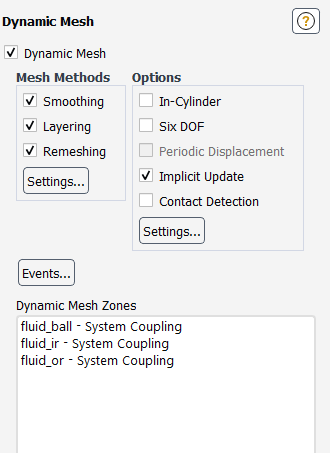
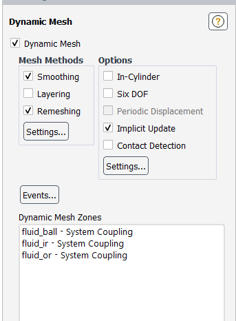
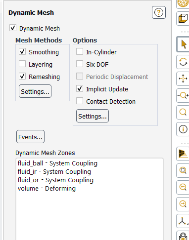
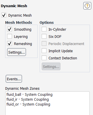
by the way, please do not activate all mesh method options as it'll likely result in unpredictable behaviour. Most likely you need smoothing and remeshing only. Deactivate layering.
-
November 5, 2024 at 7:49 am
ashishkumar.gupta
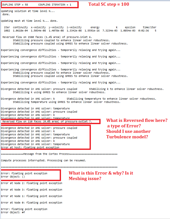
SubscriberHi Paul, I am getting Floating Point Exception Error. My Simulation ran for 50% though after running for 30 hours. I do not undertstand what is the profble here
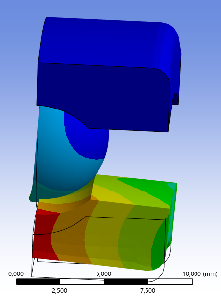
Weird Results (only 50% solved): -- > I do not see Rotation of IR. Just IR is moving Radially in X-Direction because of Force.
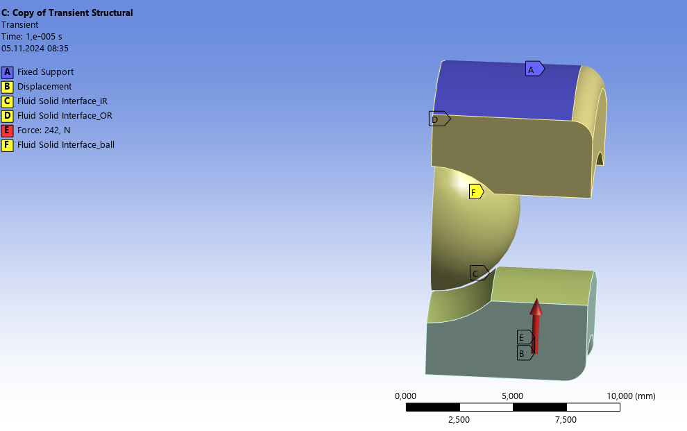
Mech Setup:
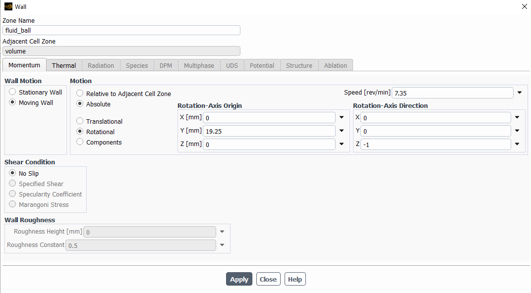
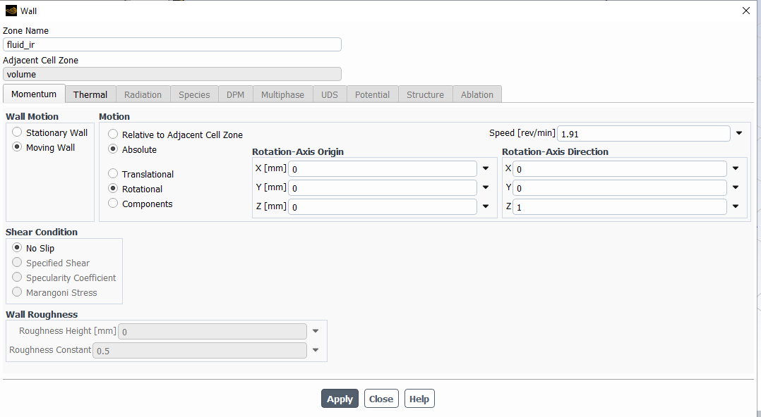
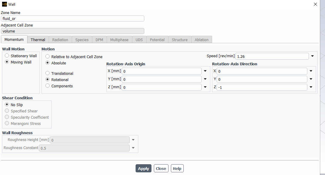
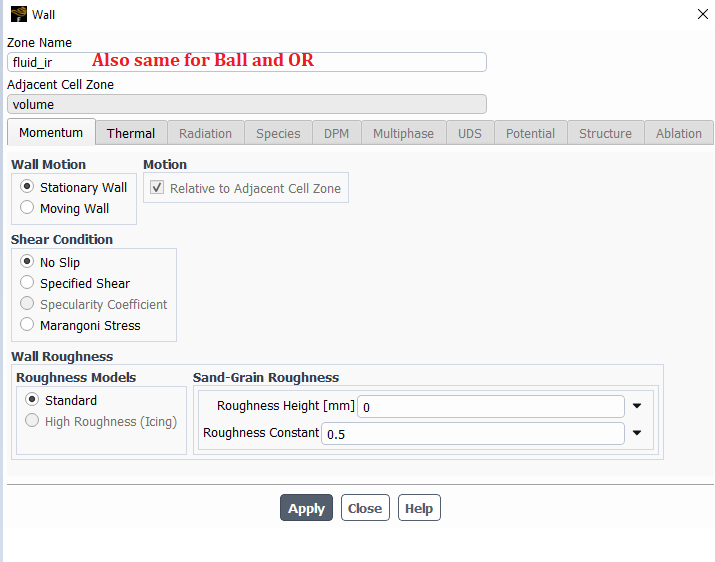
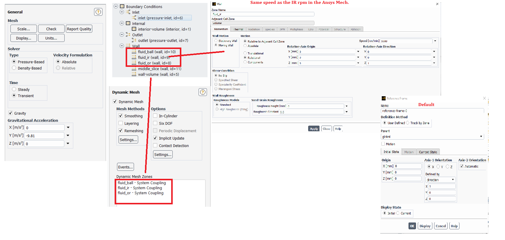
Fluent Setup:
Can you please have a quick look on this? Thank you !!!
-
November 5, 2024 at 9:00 am
Paul Hutcheson
Ansys EmployeeHi Ashish,
Reversed flow is flow either coming into the domain from an outlet, or flow going out of the domain at an inlet. It's not necessarily a bad thing.
The floating point error is most likely a symptom of divergence, possibly from poor mesh quality. You need to be monitoring mesh quality as the mesh deforms. If the quality is deterioating too much the solver won't converge. If quality becomes poor you need to check the dynamic mesh setup and monitor how the mesh is deforming. Maybe you need to allow the mesh to slide on some walls adjacent to mesh motion. I can't comment further without seeing how the mesh is deforming.
As for why the IR is not rotating, is it being rotated in Mechanical? I don't see any boundary condition applied to it. For rotating machines, we recommend rotational velocity, which will solve the IR in the rotating frame, but not move the mechanical mesh. On Fluent side of IR, it's probably best to set the wall velocity according to the rotational speed of IR and receive just the normal displacement from Mechanical.
Also the ball seems to moving across the symmetry plane, you need a symmetry boundary condition there.
-
November 5, 2024 at 12:27 pm
ashishkumar.gupta
Subscriber- Poor Mesh Quality:
I have made the mesh as fine as possible and yet the same error? Like I have create more fine mesh on Face Sizing, my software hangs out.
Also, how can I show you the video of my mesh deforming?
2. IR rotation
I discussed with other Ansys CS and also confirmed with you to give CIRCUMFERENTIAL DISP to IR instead of Roational velocity. You said it is FINE and now you saying that might be the problem?
Because in Mech standalone model with Frictional conatct, I was able to see the motion. And you said it is Fine to give IR, OR and ball surface in Fluent as STATIONARY WALL B.C with No SLIP.
You mean to say that my set up is wrong?
I am really confused now with what is happening....
-
November 5, 2024 at 12:39 pm
Paul Hutcheson
Ansys EmployeeI don't remember discussing circumferential displacement, but yes I think rotational velocity is better. Otherwise the IR will move away and lose contact with the ball.
And yes apologies for changing my advice on fluent walls, but I realised a better workflow now.
On mesh quality I don't mean better mesh quality from meshing - the mesh changes when it deforms. I mean mesh quality after and during deformation.
As for how to create videos of mesh deforming I cannot go into such detail over this forum. This forum is not for training, neither even is technical support we provide commercial customers. Please send a screenshot of the mesh deforming, or create an animation in Fluent and send to me. All of this is documented in Ansys help.
-
November 5, 2024 at 12:48 pm
ashishkumar.gupta
SubscriberI was suggested that rotational velocity would not work here. I also tried that and it did not work. So I was using Displacement upto the point IR and Ball are in contact (4.3 mm Circumference).
Because if I was giving rotational velocity in Mech, the body was not responding....I wasted 6 weeks on that.
In Fluent, should I give wall Velocity = RPM as the B.C. ,,,right? then what about Ball and OR ? Becuase Ball will also rotate and OR if fixed but fluid at OR will move.
Is it not possible to keep walls of Ball and OR 'Moving' without specifying 'Speed'?
As for Mesh quality, I will look into it and update you.
-
-
November 5, 2024 at 1:00 pm
Paul Hutcheson
Ansys EmployeeThe mentioned discussion was regarding Fluent not Mechanical. I was initially not sure from what side you intended to drive the motion.
Rotational velocity is a setting in Mechanical that solves the problem in rotating frame. It does not move the Mechanical mesh.
You have to find a set of boundary conditions that makes sense for your problem. Think about what the model is doing and what is being transferred (i.e. displacement) in which direction. This is the only way to solve such problems - the model is on your side so you're in the best position to do this. If something particular is not working as expected then you can ask us. Rotational velocity does not move the mesh. This is not a problem this is a lack of product knowledge that can be addressed by reviewing the help manual.
We can't set the problem up for you, this would be a consulting project for a commercial customer. It takes time to be done properly and can't be done over a forum. I'm sorry.
-
November 5, 2024 at 3:40 pm
ashishkumar.gupta
SubscriberI guess I might have confused you. I have idea but I am not an Ansys Product expert (especially I am newbie to Fluent and FSI).
So, In Mechanical, I apply Circumferential Disp. to IR (in contact with shaft) (alternative to Rotational Velocity of body). The OR is fixed. Force is also applied to IR.
This IR moves the ball because of Frictional contact around its own axis as well as along in the orbital motion.
This concept was extended by having 0.1 mm (0.1 um in future) lubricant film between Race and ball using FSI. So the displacement transfe looks like this: Race --> Lubricant --> Ball.
this is my expectation.
But the mesh deformation of fluid and mech. at FSI is difficult to understand. That is why I was looking up for some clarity.
I have heard that Rotational Velocity is used using Joint for Ball bearings. .,..> Do u think without using joint, Rotational Velocity can be applied to my Periodic model and it will solve my other issues?
For my case, someone suggested Disp. will be helpful. that is why I proceeded with this.
-
November 12, 2024 at 11:59 am
ashishkumar.gupta
SubscriberHi Paul, any update on the issue? I am still stuck on the same issue.
Most of the FSI tutorials show the effect of Fluid on Solid. I have not found something in which Mech. body movements causes fluid to move. In my cases, fluid is present between ball and race and 0.1 mm fluid is not able to transfer the forces from IR to ball. If I make 0.1 um or 0.01 um fluid film, it is another issue with meshing and all....
…So it is quite confusing to implement this idea in Ansys even though I know the physics behind it.
Please do let me knoe if youi need more information or pictures from my side? Thank you.
-
-
November 12, 2024 at 12:20 pm
Paul Hutcheson
Ansys EmployeeHi Ashish,
It is a complex problem to handle in this way, I can only give piecemeal advice. Ideally things need to be tested.
If OR is fixed, the ball is rotating, CFD domain must be periodic but solved in absolute frame.
If IR is rotating, this is just a wall in CFD domain so a wall velocity can be applied to CFD on IR wall. Easy.
But it is therefore wrong to move the IR in Mechanical, because the meshes will no longer overlap.
This is why I prefer rotational velocity for the IR, since it doesn't move the FEA mesh.
Paul
-
November 12, 2024 at 1:27 pm
ashishkumar.gupta
SubscriberI understand your point of view.
In Mech, giving Rotational Velocity to IR, OR = fix and applying cyclic symmetry and using the beta function ...so software knows i have the complete BB model.
In Fluent, similarly cyclic symmetry can be used. In Boundary condition, IR wall = RPM of IR in Mech & OR = stationary...ball I am not sure what to do...
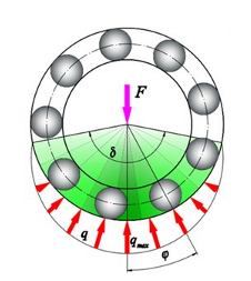
But But it is a RADIALLY LOADED DEEP GROOVE BB, so NOT all balls encounter the same load and Hence, cyclic symmetry CANNOT be used.
I have tried by giving Displacement normal to the side faces (on both side) = 0 but that did not work out.
See the load distribution curve below.
Am I missing something here? Or could you suugest something for my case to model periodic movement...
-
-
November 12, 2024 at 1:41 pm
Paul Hutcheson
Ansys EmployeeBall is a system coupling boundary, so it receives motion from mechanical where the ball is free to rotate. That's also easy.
As for cyclic symmetry, it just sounds like you just need to include more balls such that the solution remains cyclic. I.e. make a larger sector.
-
November 12, 2024 at 2:51 pm
-
November 12, 2024 at 2:56 pm
Paul Hutcheson
Ansys EmployeeThe ball is moving, so there is no need to set a velocity on the wall in Fluent.
Please understand the purpose of system coupling is to transfer displacement, so if the ball is moving in mechanical and there is a system coupling region scoped to it, it will transfer that movement to Fluent.
As for cyclic symmetry indeed, it is not compatible with SyC. You need to define it via a command snippet CPCYC instead of the cyclic symmetry object. Please check the help for usage.
-
November 12, 2024 at 3:39 pm
ashishkumar.gupta
Subscriber
-
-
November 12, 2024 at 3:56 pm
Paul Hutcheson
Ansys EmployeeAgain System Coupling is passing displacement from Mechanical to Fluent.
The setting of wall motion sets the velocity of the fluid at the wall mimicking wall motion, not the velocity of the mesh itself. In this case we will move the mesh via System Coupling, so there is no need to set wall motion in Fluent.
In case of the IR, IR is in rotating frame in Mech, so the mesh is not moving tangentially. Therefore we need a wall velocity on fluid side.
In case of the ball, ball is in stationary frame in Mech, so the mesh is moving. Therefore, we need to keep stationary wall on fluid side.
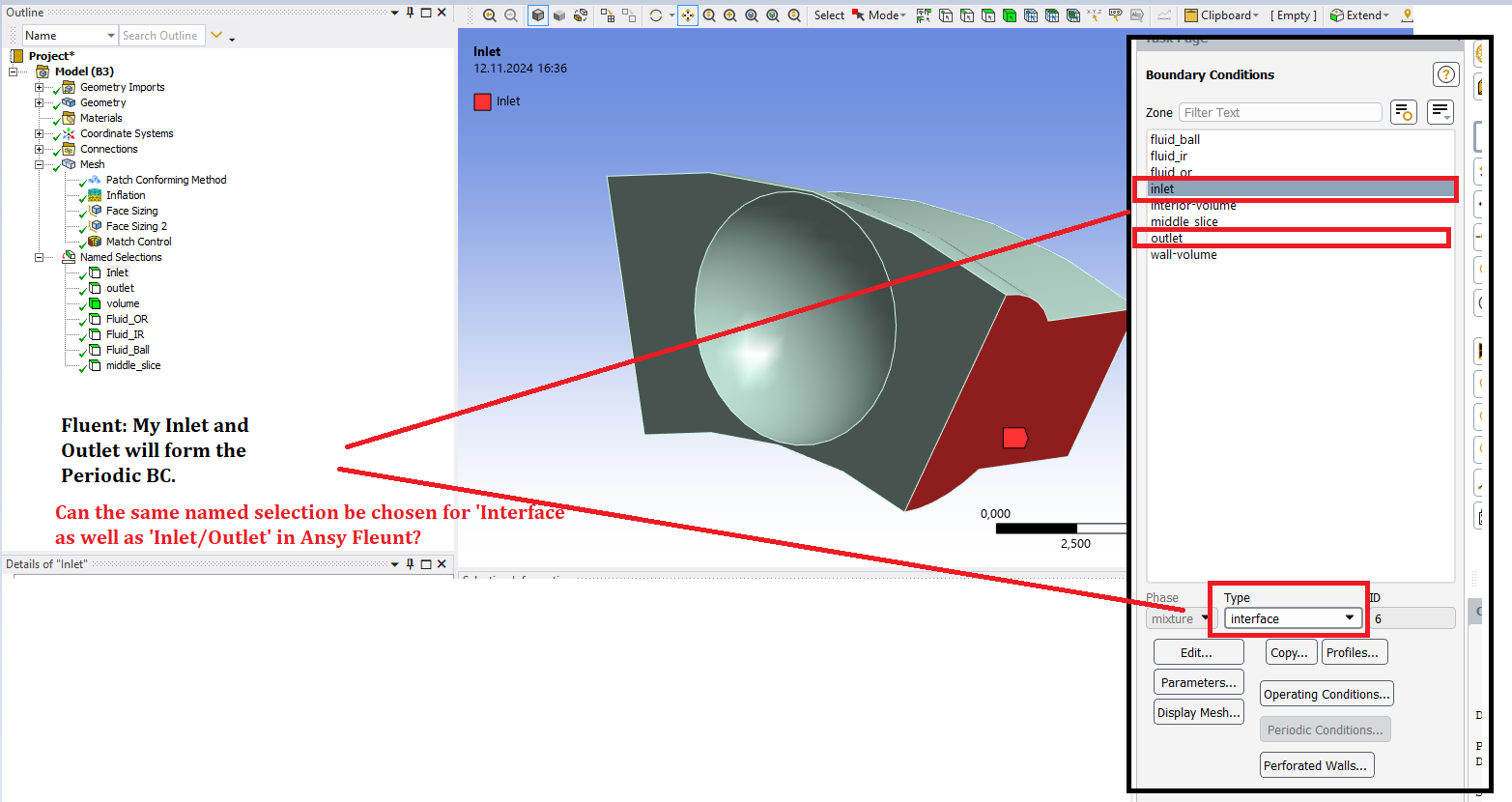
Fluent face zones can’t both be inlet/outlet and periodic no, they are different boundary conditions. If inlet/outlet are also periodic boundaries, then inlet/outlet is not appropriate because they have no relation to each other.
-
November 25, 2024 at 9:49 am
ashishkumar.gupta
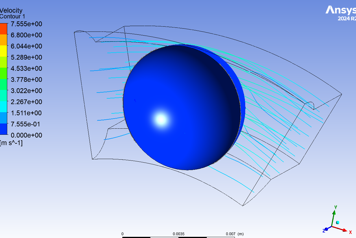
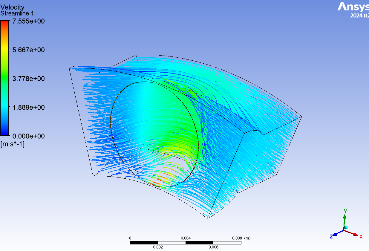
SubscriberHi Paul, Based on your suggestion, I got these results (100% completed). I did not get any Floating point exception/mesh issue in Fluent.
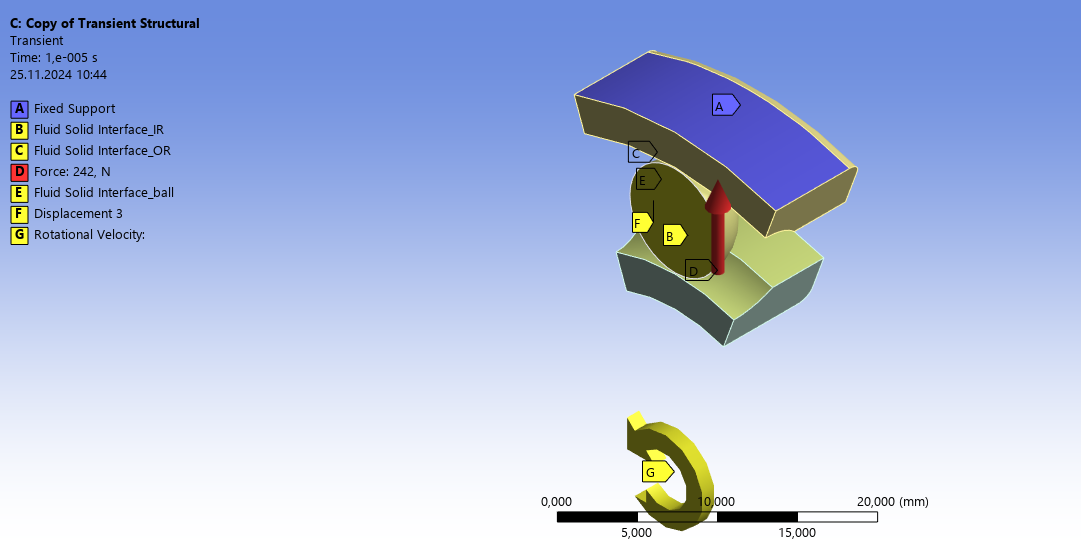
Also attaching SS of BCs for ur reference.
Mech:
Force 242 N
IR 100 RPM (Rotational velocity
OR Fixed
3 FSI
ball z disp = 0Cyclic Symmetry used in Mech
Fluent:
Inlet/Outlet flow
IR - Moving 100 RPM
OR in Fluent - Stationary
Ball - Stationary
Smoothing, Remeshing, ImplicitI do not understand why there was NO rotational movement but penetration?
-
November 25, 2024 at 10:40 am
Paul Hutcheson
Ansys EmployeeHi Ashish,
That's good news.
Why do you have a deforming volume in Fluent? All volumes are deforming by default there is no need to explicitly set it.
No rotational movement where: the ball, the IR or both?
The IR will not rotate since you are using rotational velocity, which doesn't rotate the mesh as I've said.
The ball should be able to rotate, but whether or not it does will depend on the forces it receives. Does it receive a torque from the fluid? You need to be monitoring this in Fluent.
Paul
-
November 25, 2024 at 12:19 pm
ashishkumar.gupta
SubscriberSo rotational velocity in Mech will NOT cause rotational movement of the IR ??? Then what is the use of using rotational velocity??
I want my IR to rotate in Mech --> This will cause the Ball to rotate to in Mech....See this Mech. Setup using Frictional Contact and Circumferential Disp.. ---> https://youtu.be/u3xhsZsvK2Y
Also the Races and Ball are penetrating if you see the Video URL (https://www.youtube.com/embed/G9SG7Z4Cpec)
The Ball is also not moving in Fluent.
Even tho the simulation completed, the results are pretty bad.
-
-
November 25, 2024 at 2:06 pm
Paul Hutcheson
Ansys EmployeeHi Ashish,
I explained before the purpose of the rotational velocity is to solve the IR in the rotating frame. If you move the IR mesh, it will not map correctly to the fluid zone (since the fluid zone is not moving). If you solve the fluid in rotating frame, you need to solve the IR in the rotating frame as well. The rotation of the fluid will be achieved by a moving wall velocity on the fluid side of the IR.
I thought the ball does not rotate from mechanical contact with IR but that the fluid imparts a torque on the ball since there is a fluid film in between. If it is the fluid that rotates the ball the current workflow is valid.
As for the penetration, it seems you have displacement scaling on so it is hard to see how much penetration you actually have. Penetration is normal for contact regions, this is how contact works, but it should be small compared to the displacement.
As I said, if the ball is not rotating, you have to find out why. Is the ball receiving a torque from the fluid? Then go from there.
Paul
-
November 26, 2024 at 11:57 am
ashishkumar.gupta
SubscriberHello Paul,
That is how the BB works (just in case if there might be some misunderstanding). The Inner Race (IR) causes the Ball to move becuase of Frictional ocntact between them. The Outer Race (OR) are fixed to the Housing.
In order to reduce this friction, we provide Lubricant in these BB. So my work is to ASSUME that there is always Lubricant Film ( 1mm to 1 um range) between Ball and Races (IR & OR)..
You are right ---> ''I thought the ball does not rotate from mechanical contact with IR but that the fluid imparts a torque on the ball since there is a fluid film in between. ''
Force/Kinematics Transfer: IR - Lubricant - Ball - Lubricant - OR
In reality, the Mechanical objects makes the Fluid move. So Mechanical is the Driving Factor.
Most of the FSI (or which u also assuming here), Fluid is the Driving Factor ..(like water flowing in the pipe).
So is it possible in Ansys FSI to mechanically move the objects --> causing fluid to move. This means the contact zone are always changing.
What should I do so as to replicate this animation in Ansys FSI??
I guess the Ball is receiving the Forces....
-
November 26, 2024 at 12:57 pm
Paul Hutcheson
Ansys EmployeeAre you not modelling the lubricant in CFD? Is it just air? Sorry I misunderstood this.
If you are not modelling the lubricant film I agree, you need frictional contact to drive rotation instead. If you can assume no mechanical slip/lubricant slip, you can choose "rough" contact, which will rotate the ball exactly at the same speed as the IR with no slip. Otherwise this is a modelling uncertainty and the ball may drift as I think I saw in one of your videos.
Do you want to create an animation or find an engineering solution? You can do it all with moving mesh but it won't be as efficient to run as you'll need the full 360 deg. or rotate both fluid and mechanical sectors, possibly leading to errors down the line. This is why we solve rotating cases in rotating frame wherever possible.
As for the fluid forces, you need to monitor the ball torque. It's not possible to evaluate whether or not the ball should move based on the velocity or pressure field. We can imagine, but with the torque, and the rotational moment of inertia we can predict the rotation of the ball and know if it's a setup error or not.
Paul
-
November 26, 2024 at 2:26 pm
ashishkumar.gupta
SubscriberAnimation was just for representation so u understand the KINEMATICS of BB and my requirements.
Obviously, I want to model an engg. solution using 2 way FSI in Ansys.
This is what I have modeled in Ansys Mech. and Fluent. I have kept the contacts Frictionless as the Ball and Races will never touch each other. They will always be separated by a Lubricant Film between them.
I hope I was able to convey my problem to you and hope to receive some feedback to set-up this FSI in Ansys.
I have asked around and some suggested that Ansys might have limitations to not be able to perform the 2 way FSI when -- > 'Mechanical objects makes the Fluid move. So Mechanical is the Driving Factor.'
-
November 26, 2024 at 3:44 pm
Paul Hutcheson
Ansys EmployeeOf course Mechanical can drive fluid motion, this is what system coupling is used for.
So if your fluid is oil, what is the lubricant? If is just the oil film in between, then you don't have mechanical contact. Neither in reality nor in the simulation. Frictionless support is ok in this case, to prevent fluid mesh collapse by using an offset as discussed previously.
I have given you all the details required now to setup this FSI case.
Here remember we have set a wall velocity on the IR in Fluent. This will create flow, you could say the lubricant flow. This flow will create a shear stress on the ball FSI interface. This shear stress will create a torque on the ball and cause it to rotate. I recommend constraining the ball to rotate only about its rotation axis (z). Either a revolute joint (ground to mobile) or a remote displacement with only rot Z free. Then the ball can only rotate!
If the ball is not rotating, you need to measure the torque as I said and work out its expected motion.
-
December 9, 2024 at 9:42 am
ashishkumar.gupta
SubscriberHi Paul,
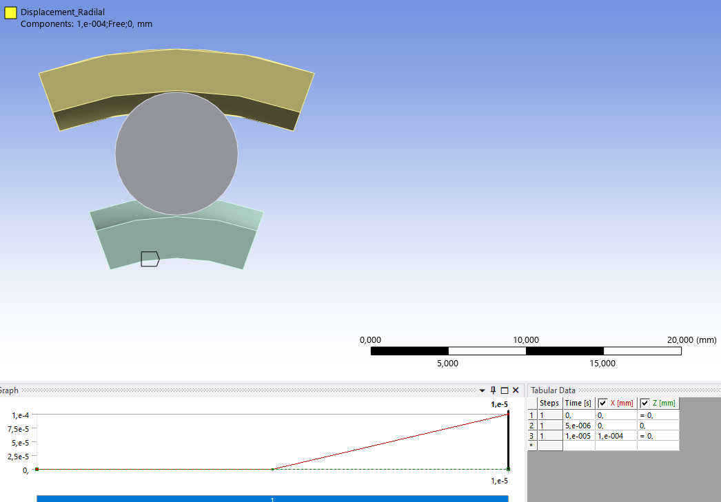
Even though I used ‘Pure Penalty with Normal Stiffness factor=10’ contact, I can see penetration in the AUTO SCALE VIDEO
Max. penetration ~ 1E-07 mm; Max. Total deformation ~ 1E-04 mm; Gap = 0.1 mm ; penetration/Total deformation % = 0.1% -----> is it acceptable or more?
Here is the YT link where you can see the Ball and Race penetrating…Also, I do not see Rolling movement of Ball and Races here.
B.C. for your reference:
Mech:
IR 1000 RPM (Rotational velocity)
$ Radial Disp. for IR (0 step = 0 mm; 50th step = 0 ; 100th step = 1,e-004 mm) ….0.1 mm is gap between Ball and RaceFluent:
Fluid Speed at Walls of: $ IR – 1000 RPM
Ball – Stationary
OR – StationaryAm I doing anything wrong here?
-
December 9, 2024 at 10:04 am
Paul Hutcheson
Ansys EmployeePenetration of 0.1% is acceptable. As I said before visualising penetration/deformation with auto scale is unreliable since you are looking at a scaled/exagerrated result.
I don't really have enough info to judge what is going on and why. Is the radial displacement coming from SyC or applied in Mechanical?
Why are the balls moving tangentially if you are solving the problem in rotating frame? As I said it's best to restrict the ball to have 1 rotational DOF free, then likely they will rotate.
I cannot judge whether balls rotate from the video. You need to look at the ball torque as I keep saying... also put a coordinate system on the ball and measure the rotation directly.
Paul
-
December 9, 2024 at 11:46 am
ashishkumar.gupta
SubscriberRadial displacement is applied in Mechanical on Inner Race (bottom face):
Ball Remote Disp. around its own axis: -- > Ball is restrctied and it should Roll or Rotate aroud its own axis. But it is just moving tangentially becuase the Forces of Fluid in Fluent > Ball Rotation Speed.
Regarding --> ''You need to look at the ball torque as I keep saying... also put a coordinate system on the ball and measure the rotation directly.''
I am still trying to figure out how I can see that in the Resuts..
-
-
December 9, 2024 at 1:46 pm
Paul Hutcheson
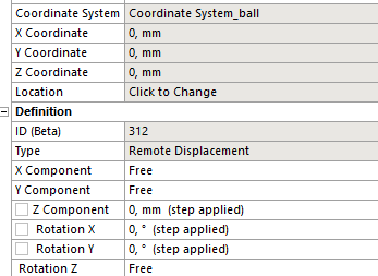
Ansys EmployeeThe remote displacement on the ball should have UX,UY,UZ,RX,RY=0 and only RZ free.
-> It is very easy for me to lose track of the setup you have supporting you in this way. Please make sure you are solving both CFD and Mechanical in a rotating reference frame, and adjust all boundary conditions at walls accordingly.
To calculate the ball torque, firstly create a cylindrical coordinate system in Fluent, then calculate the moment about z axis. This is the torque.
In Mechanical you can calculate the rotational z displacement once you have a cylindrical coordinate system in Mechanical.
Paul
-
December 9, 2024 at 3:12 pm
ashishkumar.gupta
Subscriber' Please make sure you are solving both CFD and Mechanical in a rotating reference frame' ---> means IR in Mechanical has Rotational Speed and Fluid wall speed of IR in Fluent also has same RPM....right?
'o calculate the ball torque, firstly create a cylindrical coordinate system in Fluent, then calculate the moment about z axis.' ...I DO NOT have Ball in the Fluent modeled.
IR, Ball, OR = Modeled in Mech. && Fluid (also called Lubricant) = Modeled in Fluent
-
December 9, 2024 at 3:48 pm
Paul Hutcheson
Ansys EmployeeYes for Mechanical, no for Fluent.
You have to understand principles such as rotating reference frames and how they are applied to the solvers in order to complete this project. I can't go through every detail in this forum I'm afraid.
A moving wall in Fluent doesn't mean a moving reference frame. A moving reference frame means you solve the fluid equations in rotating reference frame following the IR (i.e. rotating at the same speed). This is set under frame motion in Fluent.
If you use frame motion, then it will be OK to change the IR wall speed back to stationary (relative to adjacent cell zone - which will now be rotating with IR). Sorry for changing this again, but it is not always clear the setup you currently have and supporting it via this forum chat alone is not easy. I think we're getting there.
If you don't have the ball wall in Fluent then the ball will receive no fluid forces and will not rotate. I don't understand why you don't have the ball included in the fluid? I think you need to share your full boundary conditions on fluid side please.
Paul -
December 9, 2024 at 4:15 pm
ashishkumar.gupta
SubscriberI thought the Body in Mech. should have same fluid wall speed in Fluent.
Typically, IR should rotate at 1000 RPM. OR can be Fixed Support. The Ball will rotate becuase of Force transfer through Fluid forces.
B.C. in Fluent:
I have never heard of FRAME MOTION in Fluent in any of the videos/post. Where exactly is this option available?
-
December 10, 2024 at 9:45 am
Paul Hutcheson
Ansys EmployeeThanks for the pictures. Why do you have an inlet and outlet there? Isn't the flow driven by IR rotation? Rotational periodic boundaries would be better in that case.
Please search the help manual to familiarise yourself with these concepts:
https://ansyshelp.ansys.com/public/account/secured?returnurl=/Views/Secured/corp/v242/en/flu_ug/flu_th_sec_srf_fjk.html?q=frame%20motion
Frame motion is under cell zone conditions for the fluid zone.
I see you do have a wall representing the ball, so you can calculate the torque on it.
If you solve in a rotating frame, make sure the wall boundary conditions are correct for that frame. E.g. the IR will now be stationary relative to adjacent cell zone, and OR will be counter-rotating with IR velocity relative to adjacent cell zone, or stationary in absolute frame.
-
December 23, 2024 at 8:37 am
ashishkumar.gupta
SubscriberI have implemented as u suggested……stuck at one place due to complicted kinmematics…...check the details below/above...
-
-
December 23, 2024 at 8:36 am
ashishkumar.gupta
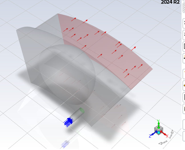
Subscriber3D view of Fluid in Fluent:
Front View:
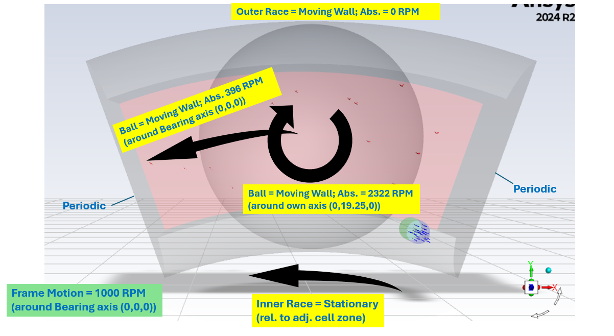
I have given the 2 side faces as PERIDOIC FACES. I have given Frame Motion = 1000 RPM around Z axis under the cell zone.
It is bit complicated now. I do not have any problem assigning WALL SPEED to INNER RACE and OUTER RACE.
But my Ball ROTATES around its own axis (0,19.25,0) as well as REVOLVES around the bearix axis (0,0,0) (as u can see in the figure above)
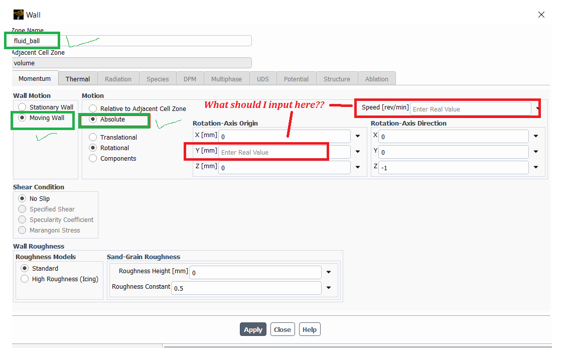
M question is how can I assign both the speed to the SAME BALL FACE in the Ansys Fluent Boundary Condition?
Thank you!!
-
December 23, 2024 at 9:29 am
Paul Hutcheson
Ansys EmployeeThe ball rotation should be relative to adjacent cell zone, not absolute - since the ball is moving also with the IR.
The speed you put is then the rotational speed of the ball in the rotating frame of the IR.
-
December 23, 2024 at 9:32 am
ashishkumar.gupta
SubscriberI get that....but the Ball ROTATES around its own axis (0,19.25,0) as well as REVOLVES around the bearix axis (0,0,0) ....
How can I achieve that?
-
-
December 23, 2024 at 10:25 am
Paul Hutcheson
Ansys EmployeeHang on a minute - do you want to set a velocity here for the ball wall?
The ball is a system coupling boundary, so the mechanical ball is free to rotate and will send displacements to Fluent.
If the ball receives a torque from the fluid, it will rotate, and move the mesh in Fluent.
So in this case you want to keep stationary ball wall relative to adjacent cell zone.
You also need to have a dynamic mesh setup in Fluent that is prepared for the ball rotation. So long as the ball will only rotate in Fluent (and not translate), sliding mesh or overset would be sensible. We discussed this is an option using remote displacement or revolute joint in mechanical.
-
December 23, 2024 at 1:01 pm
ashishkumar.gupta
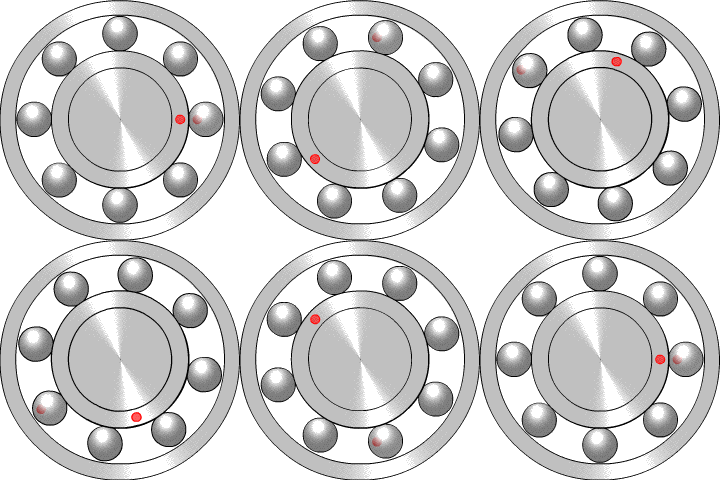
SubscriberFollow the red dots in the animation....
” So long as the ball will only rotate in Fluent (and not translate), sliding mesh or overset would be sensible”
— 1. I want the ball to ROTATE as well as TRANSLATE (as shown in animation)
— 2. I am NOT using sliding mesh or overset . I am just using Dynamic Mesh (smoothing & Remeshing) & Moving Reference Frame in Ansys Fluent
Are these B.C.s perfect for 2 way FSI of Ball Bearing motion?
-
December 23, 2024 at 1:27 pm
Paul Hutcheson
Ansys EmployeeIn the reference frame of the IR, the balls are not translating.
The animation you show shows motion in the absolute frame. You are not solving this problem in the absolute frame.
Your Mechanical setup should also reflect this. Only RZ should be free, the other 5 DOF should be fixed.
You can check if remeshing is sufficient indeed.
-
December 23, 2024 at 1:30 pm
ashishkumar.gupta
SubscriberGot you!!
But I want the balls to translate....Then in which Reference Frame should I solve my problem?
-
-
December 23, 2024 at 1:33 pm
Paul Hutcheson
Ansys EmployeeHow do you want them to translate?
If only as shown in your animation, as I said if you solve in the reference frame of the IR, there is no translation here.-
December 23, 2024 at 2:00 pm
-
-
December 23, 2024 at 1:38 pm
Paul Hutcheson
Ansys EmployeeI'm not sure you've understood yet what it means by solving in a rotating reference frame. Please look at this as it's critical for your project.
-
December 23, 2024 at 1:54 pm
ashishkumar.gupta
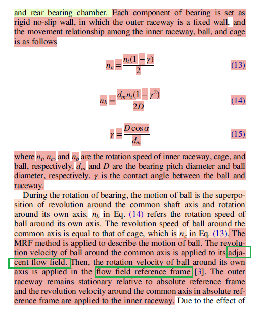
SubscriberI have read about the RRF and MRF. For my case, it is to solve the equation of motion in the IR Reference frame (which rotates with the IR in mechanical).
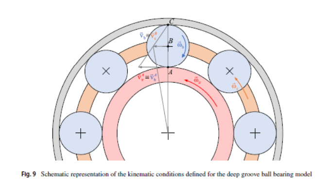
But the Ball will still translate and rotate w.r.t Inner Race referece Frame. (as the Cage is not present in my case to translate the ball)
Outer Race will move in the opposite direction w.r.t Inner Race reference Frame.
In the Pciture below, The Cage (w_c) rotating casuses the ball to translate/guide along the circumferece. That is missing in my case!!
If the ball does not translate, I cannot capture the correct Lubrication Dynamics and Effects on surface of Raceway.
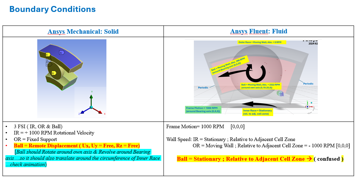
So translation of ball is important for me. That is why I have these B.C. in Mechanical:
•IR = + 1000 RPM Rotational Velocity•OR = Fixed Support•Ball = Remote Displacement ( Ux, Uy = Free, Rz = Free)I want you to help me with the Wall Speed of all this objects (IR, OR and Ball) in the Fluent for this case?
-
-
December 23, 2024 at 2:58 pm
Paul Hutcheson
Ansys EmployeeHi Ashish,
Ok I’m a bit surprised, as in the animation you wanted to follow there was no ball translation, and previously we were proceeding on the basis that the balls were rotating with the IR (as in the animation).
So what you’re saying is the balls do not rotate with the IR speed, but at a speed slightly different due to some slipping? This is not going to work with the domain you have currently, as the ball will move out of the domain and lose contact with the surrounding structure(!).
Is this ball motion pre-defined, or do you want to predict it?
If it’s pre-defined/constant, you could solve the whole problem in the reference frame of the ball, since IR and OR are surfaces of revolution.
Then you need to adjust wall boundary conditions accordingly.
If this new ball motion is an output not an input, I think the only solution is to model the full 3D geometry – but prediction of such motion will be extremely complex and prone to divergence – I wouldn’t recommend it with this type of high fidelity FSI approach.
Paul
-
December 23, 2024 at 4:43 pm
ashishkumar.gupta
SubscriberHi Paul,
‘So what you’re saying is the balls do not rotate with the IR speed, but at a speed slightly different due to some slipping? ‘
– YES different SPEED without slipping
You guessed it right. We input Inner Race (1000 RPM) and Outer Race(fixed support) and Frictional contacts between Ball and Races make it rotate and translate ….this is in pure only Ansys Mechanical Simulation (NON-FSI)
Now, In 2 way FSI, we have very thin film of Fluid between Ball and Race , which leads to FrtictionLESS contact and FSI helps in the Transfer of Forces between Mechanical (Ball/Race) and Fluent (Fluid) to make Ball rotate and translate.
’This is not going to work with the domain you have currently, as the ball will move out of the domain and lose contact with the surrounding structure(!).'
— I Simulate it for very short time till they are all in contact with each other. I can calculate that time too. In addition, we can use Cyclic Symmetry and Periodic B.C….So its is a CLOSED LOOP….
‘Is this ball motion pre-defined, or do you want to predict it?’
– Can be both. it is constant angular velocity concept, so the RPM of all objects (IR, OR, Ball) can be calculated mathematically and if needed, can also be provided as Input [ But in pure Ansys Mechanical Simulation (NON-FSI), Ball movement is the OUTPUT]
‘If it’s pre-defined/constant, you could solve the whole problem in the reference frame of the ball, since IR and OR are surfaces of revolution.
Then you need to adjust wall boundary conditions accordingly.’
How can we do it? that is what I am confused now. Because I thought the FSI can make the ball rotate & translate but it was not able to.
If I want to give wall speed to Ball, I am unable to give both the Rotational Speed & Revolutional Speed.
Is there any other alternative to make it work?
-
December 23, 2024 at 6:00 pm
-
-
December 23, 2024 at 4:59 pm
ashishkumar.gupta
SubscriberAlso, just to recall, In FSI,
my SOLID parts (Ball, IR, OR) are supressed in the ansys Fluent.
my Fluid is supressed in the ansys Mechanical
So when we apply Wall Speed to different faces of FLUID in the Ansys Fluent, is that what the tutorial also demonstrates about MRF/RRF?
Because in the video/blogs, they actually apply Wall Speed to faces of the SOLID components as the whole system is solely solved in the Ansys Fluent,...
Am I right??
-
December 24, 2024 at 9:41 am
Paul Hutcheson
Ansys EmployeeHi Ashish,
Sorry, I cannot solve your problem for you. We would normally charge commercial customers for this. I have told you enough about how Fluent and Mechanical are working now to set boundary conditions that are consistent with whatever frame of reference you use. You have to think about that for yourself.
I recommend defining your problem in a way that can be solved, otherwise you risk completing nothing in the end.
It sounds too complex to include the slip of the balls, especially if it's only for a short time(!). I would continue with a single frame of reference as we've talked about so far, and then consider slip later in the project as a separate investigation. This should have been mapped out better from the beginning of your studies.
I'll be away for 1-2 weeks now, so I wish you luck and happy holidays.
-
December 24, 2024 at 9:48 am
ashishkumar.gupta
Subscriberokay Paul!! Thank you for all the consitent help you have provided. I cannot thank you enough for your dedication as a CS.
I will take your opinoin into consideration by using just SRF and no translation of the ball....I hope I can make my student project work with this!!
Have a great vacation, Merry Christmas and Happy New Year in advance!!
-
- You must be logged in to reply to this topic.


-
5024
-
1714
-
1387
-
1248
-
1021

© 2026 Copyright ANSYS, Inc. All rights reserved.

