-
-
November 23, 2018 at 2:11 pm
José Mantovani
SubscriberHello guys! I try to make a simulation of classical Turbulent Channel Flow.Â
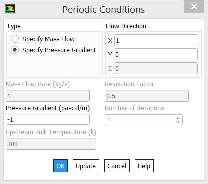
I'm basing my simulation on the work of Moser and Kim (1999) and I want to simulate for Rethau values equal to 180, 300, and 590. I found, as it seems, a PowerPoint presentation from Stanford University with comments and data on how to model this type in the images below. In the image have the boundary conditions used, material parameters, initial conditions, solver setup, etc..Â
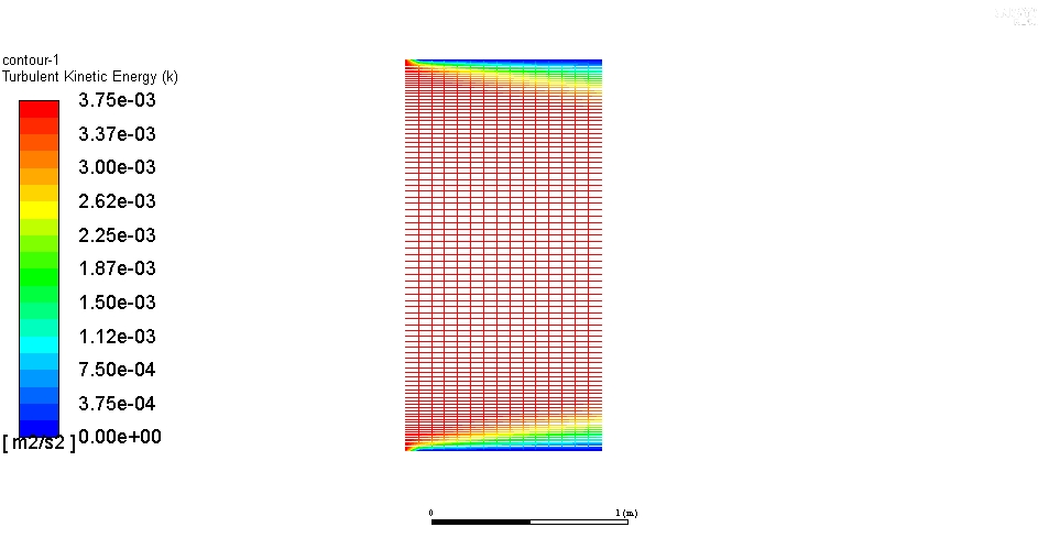
So I use same initial conditions, same geometry dimensions, a similar grid and k-epsilon with enhanced wall treatment. And I get the results in the image below.Â
As We can see in the first image (that I get in the internet) the TKE Contour looks like a channel flow in a downstream region, but my TKE Contour looks like a upstream region (as if the flow were coming out of a tank and flowing into the channel). By this (and other divergences, like the values of TKE), I have some questions:
- How Can I input the initial conditions: inlet and outlet conditions as a Periodic Boundary Conditions?
-Â What do I need to change to make my simulation look like the first image?
-Â The variable y + by default already has in FLUENT, how can I insert the variable u +? (I ask this because I found several formulas on the internet).
-Â How can I compute the value of uthau and Rethau to ensure if I have the values I want?
I decided to test this in a simple 2D simulation to understand this issue of periodic boundaries and how to model a zero pressure gradient in order to heal my doubts and be able to perform this 3D simulation using LES.
I am immensely grateful for those who read and help me, I hope this helps other users in the community.
Thanks,
Mantovani.Â
Â
-
November 23, 2018 at 3:57 pm
Rob
Forum ModeratorFor periodics build a model and set the upstream & downstream surfaces as type interface in Meshing (ideally with different names) and make sure the mesh is about the same. In Fluent look at teh Mesh Interfaces and Periodic.Â
Periodic settings are in the Boundary Conditions section, look in the options below the list of boundaries. Not sure about LES and periodics as you may have eddies larger than the domain length - test with RANS to see how it works and then experiment.Â
Assuming the u+ value has a formula you can use a Custom Field Function. Use x or y coordinate as the wall distance function, remember to correct for the model position!Â
-
November 23, 2018 at 4:29 pm
José Mantovani
SubscriberThanks to reply rwoolhou, I will try and soon I share here.Â
When I load the geometry in Meshing and I mesh using Edge Sizing, after that I click on the lines and I set the horizontal as wall and vertical as inlet and outlet. How did you say this process of naming the boundaries changes? Should I interface? Sorry, I did not understand correctly. I need first define the line as interface in Ansys Meshing? How make this? I see this image below in Google, but I don't find in FLUENT.
Mantovani.Â
-
November 23, 2018 at 5:26 pm
Rob
Forum ModeratorIn ANSYS Meshing set the named selection as interface, and Fluent will pick that up. The panel may be slightly different in Fluent, but you can find the interfaces in the list on the left side of the Fluent window.Â
-
November 23, 2018 at 5:50 pm
José Mantovani
SubscriberThanks one more time rwoolhou. I do and now its work. But, now I need set u+ formula, can you help me? Look in image below the results for u velocity and tke contours and a xy plot of u+ vs y+ and how I define the u+.Â
I am doing something wrong, the graph does not appear at all with what I found on the internet ... In the file it does not indicate the values of k and epsilon or turb intensity ...
Thanks,
Mantovani.Â
-
November 23, 2018 at 8:37 pm
Amine Ben Hadj Ali
Ansys EmployeeUplus is the ratio of the bulk velocity to wall stress velocity or the use of the equation from Fluent to get ustar. -
April 24, 2020 at 11:10 am
IRobin
SubscriberHi all,
I know this is an older post but I would like to achieve the same result as José mentioned. I followed all steps pointed out by rwoolhou, but my solution does not converge no matter what I try. I used the exact same values as given in the PowerPoint of the Stanford University (density, viscosity, length width, etc...) I have attached some pictures of the settings I used:
And for the periodic boundary condition I use:
When I monitor the maximum velocity value at one of the periodic boundaries, it shows an increasing trend no matter how long I iterate. The residuals are not showing anything better:
Although the residuals start to behave a bit after longer iterations, it is not seen back in the velocity control point (keeps increasing). I also tried to lower the pressure drop (to values of -0.008 Pa/m), specify a mass flow, but the velocity keeps on increasing every simulation no matter how long it iterates... Such an 'easy' problem should not take that many iterations, or does anyone have an idea of what I am doing wrong?Â
Â
Kind regards,
Â
Robin
-
April 24, 2020 at 2:57 pm
Rob
Forum ModeratorWhy are you using a negative pressure drop over the section?Â
-
May 13, 2020 at 2:11 pm
IRobin
SubscriberDear rwoolhou,
I used both positive and negative values, but the result did not change. The reason why it is negative is that I expect a negative pressure drop (flow from left to right). But to come back to the simulation, I seem to be unable to get a converging and mesh independent solution. After 100 000 iterations, one of my meshes finally converged. But when I refine further, this iteration number went up even further. Note that I also used a first guess of the velocity field, otherwise it would take even longer.... It just seems strange that such a trivial problem takes so many iterations before it converges.
Robin
-
May 13, 2020 at 3:30 pm
Rob
Forum ModeratorThe value is the "drop" so with a negative I'm not sure what the maths will try and do: possibly a pressure rise!Â
If you put a velocity bc at one end and pressure at the other does it work? I'm not too worried about the accuracy, this is to check the mesh.Â
-
May 13, 2020 at 4:14 pm
IRobin
SubscriberDear rwoolhou,
When using a velocity inlet (u_x =Â 1.0 m/s) and a pressure outlet (p=0), I get an (almost) instantly converged solution (monitored values do not change after 30 iterations). I have attached the velocity and turbulent kinetic energy below:
These results are identical (almost to the last digit) to what José Mantovani illustrated at the top/beginning of this post. He then solved it by using the periodic boundary conditions... But this seems to fail when I try it. Ones again, if I simply change the inlet/outlet BC to interface's and enable the (translational) 'periodic boundary' for both via the interface menu + set a pressure drop of 0.1. I get an infinitely increasing velocity..
RobinÂ
-
May 13, 2020 at 6:18 pm
Kalyan Goparaju
Ansys EmployeeHello Robin,Â
When you run long enough, due to the specification of translational periodic boundary condition with a pressure drop, the flow will actually attain what is called a fully developed state. It could happen that the residuals might converge to a value of 1e-3, but the velocity can still keep increasing. This is an indication that the problem hasn't yet attained an equilibrium state.For such problems, don't just base the convergence on residuals alone. Instead, run the simulation for as long as the monitors to reach a plateau. For this, I would recommend either turning off the residuals or further lowering the threshold to say 1e-5 or 1e-6.Â
Thanks,Â
Kalyan
-
May 14, 2020 at 9:38 am
IRobin
SubscriberDear Kalyan,Â
Thank you for your reply. I indeed lowered the residuals such that they don't stop/influence the simulation. As I mentioned, I did also monitor points of interest (like the maximum velocity, average mass flux) and noticed that these have a hard time obtaining a plateau. For example, for a mesh with roughly ~10000 elements, it took well over 120 000 iterations before I noticed a plateau. Then again, it still required additional computation to verify whether this was indeed a plateau. I have run multiple simulations of different kinds with ANSYS Fluent in the past year and never encountered one which took this many iterations while being such an 'easy' problem. Hence I wanted to make sure I did not do anything wrong.
Robin
-
May 14, 2020 at 1:34 pm
Kalyan Goparaju
Ansys EmployeeHello Robin,Â
Though your setup is correct, I agree with you, 120,000 iterations sounds too much for this problem. Are you using a coupled solver? Did you turn on pseudo-transient? Can you perhaps try increasing the time scale factor to 3 or 5 and see it if helps achieve a faster convergence?
Thanks,Â
Kalyan
-
- The topic ‘Turbulent Channel Flow: Some questions’ is closed to new replies.
- How do I get my hands on Ansys Rocky DEM
- Unburnt Hydrocarbons contour in ANSYS FORTE for sector mesh
- Script Error
- Help: About the expression of turbulent viscosity in Realizable k-e model
- convergence issue for transonic flow
- Facing trouble regarding setting up boundary conditions for SOEC Modeling
- Point exception in erosion calculation
- Errors with multi-connected bodies using AQWA
-
2257
-
919
-
599
-
591
-
497
© 2025 Copyright ANSYS, Inc. All rights reserved.