-
-
March 28, 2024 at 10:10 pm
jc47948
SubscriberHello,
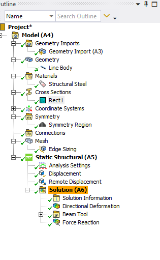
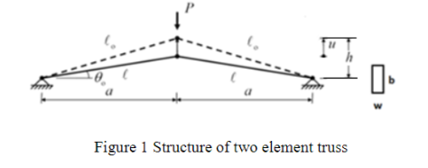
I am trying to model a simple two bar truss pinned at both ends with a displacement at the top. I am trying to do it with just one bar element using symmetry at the top vertex. The pinned support is a remote displacement which only allows rotation at the Z-axis. I'm guessing the symmetry is considering the joint bonded, though I'd like it to allow rotation like the pin. Is this possible? In the current configuration it looks like the resultant force compressing in the X direction gets extremely high. Though...maybe it should?


-
March 28, 2024 at 11:49 pm
peteroznewman
SubscriberWhat are the results if you don't use symmetry and instead have two truss elements? Why do you even want to use symmetry?
If you have truely used truss elements and not beam elements, there are no rotational degrees of freedom, only translational degrees of freedom exist in truss elements.
-
March 29, 2024 at 12:57 am
jc47948
SubscriberHi Peter, thanks for the reply. This is unusual, but I need to force a two-element truss to move with displacement that is pinned at both ends. It should come together with some sort of joint. the elements should deflect but not "bend".
I cannot get it with two members either, I am very new to ANSYS. I can theoretically solve it easily enough in equalibrium, but need to make this work in ANSYS. I think I'm close, or maybe way off. I went from a complex knuckle joint (3D modelled) to a simple line structure and have been going at it for a long time.
-
March 29, 2024 at 10:47 am
peteroznewman
SubscriberClick on the Line Body, is the Model Type set to Link/Truss?
Click on the mesh, is the Element size larger than the length of the truss? Since you used an Element Size mesh control, maybe that is already set to 1 element.
Click on Static Structural, under Supports, use Simply Supported on the pinned end, use a Displacement on the center node and set X=0, Y=-1, Z=0. This is a displacement load instead of a force load, but the Y component of the reaction force shows how much force it takes to create this displacement. Since this is a half model, the full truss will take twice as much force to deflect this amount. Displacements are easier to converge than Forces. If you want to use a Force, then leave Y = Free.
Click on Analysis Settings, set Large Deflection to On.
Right Click on Solution, Insert > Beam Results > Axial Force
The Force Reaction (Total) result will show the same value as the Axial Force but with a negative sign.
-
March 29, 2024 at 11:05 am
jc47948
SubscriberAhh this helps, Thanks man!
-
-
- The topic ‘Truss Joint on Symmetry Vertex?’ is closed to new replies.


-
4683
-
1565
-
1386
-
1242
-
1021

© 2025 Copyright ANSYS, Inc. All rights reserved.


