-
-
May 28, 2024 at 12:46 pm
anjaliar
SubscriberHi,
I have been going through the example given here:
https://optics.ansys.com/hc/en-us/articles/360042328774-Traveling-Wave-Mach-Zehnder-Modulator
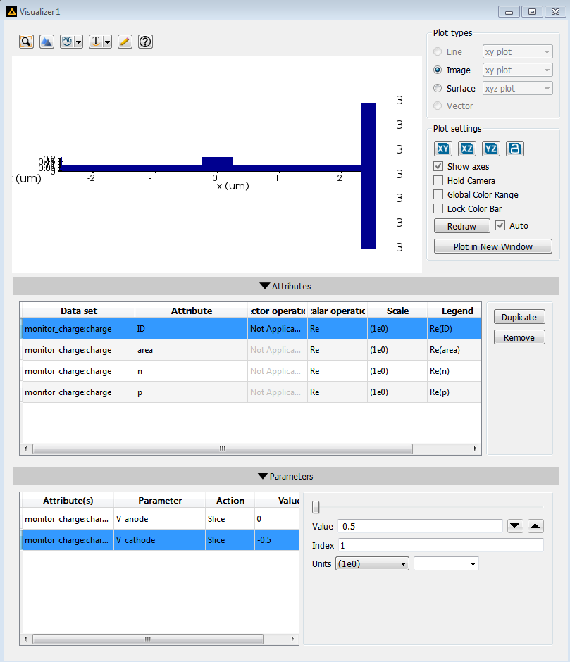
I tried the first step, i.e, running the simulation in CHARGE (without editing the example file). The results did not come up as shown in the page. There was no variation in charge with respect to change in voltage.
The result obtained is attached below (for all values of cathode voltage). Please help in figuring out the problem.
Thanks in advance.
-
May 28, 2024 at 5:48 pm
Amrita Pati
Ansys EmployeeHi Anjali,
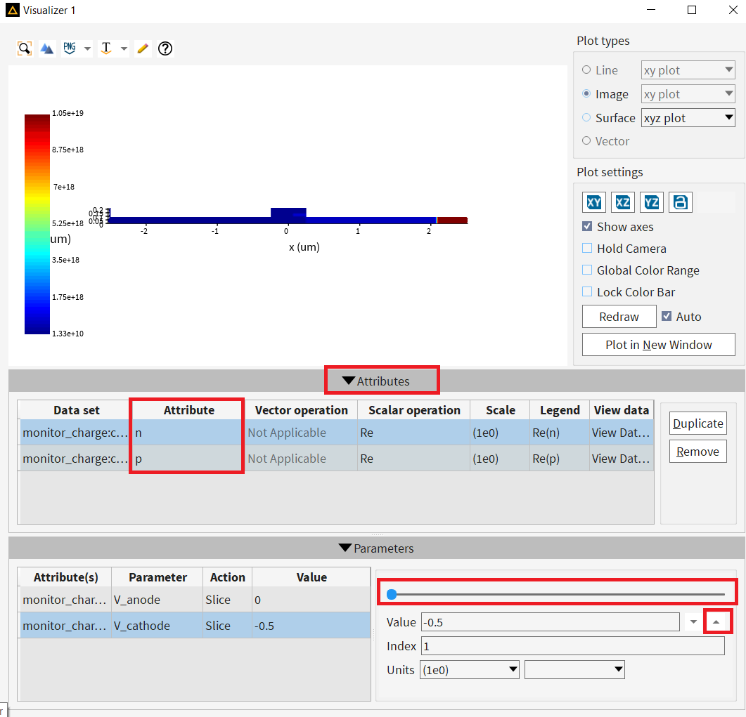
Thanks for sharing the screenshot! I will recommend you to make sure that you are viewing the correct "Attribute". From the picture, I can tell that you have selected the Attribute "ID", which tells us the domain number of a geometry. You are probably interested in "n" and "p". You can also remove the attributes such as ID and area, which you won't need most likely:

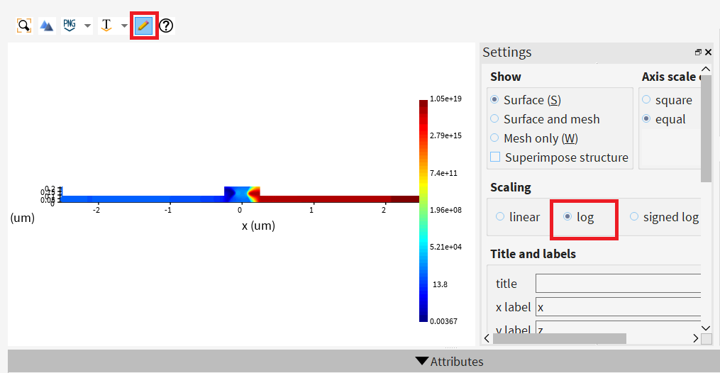
Now you can choose the "V_cathode" parameter and use the slider/up-down buttons to look at the charge density for different voltages. Another thing to note would be that, in the article, I believe they are using the log scale to look at the results, as shown below:Regards,
Amrita -
May 29, 2024 at 11:09 am
anjaliar
SubscriberThank you, Amrita.
-
- The topic ‘Traveling Wave Mach-Zehnder Modulator example’ is closed to new replies.


-
3567
-
1103
-
1063
-
1045
-
952

© 2025 Copyright ANSYS, Inc. All rights reserved.


